• Please be sure to read the rules and adhere to them. Some banned members have complained that they are not spammers. But they spammed us. Some even tried to redirect our members to other forums. Duh. Be smart. Read the rules and adhere to them and we will all get along just fine. Cheers. :beer: Link to the rules: https://www.forumsforums.com/threads/forum-rules-info.2974/

"Snowzilla": A Comprehensive Tucker 1643 Project...

No. The photos are taken with an iPhone, and uploaded to the cloud. The posts are made from my computer (Macbook).

……….. I have the same problem with pics,... lately I can only load one pic at a time... better than no pic at all,... I guess..lol…. I love the custom hyd pump bracket.....Sweet,....
 
Snowzilla work resumes. Actually, it resumed some time ago…

Both Thundercat and Snowzilla got upgraded with Eaton E-Lockers in their differentials. These aren’t cheap, but in certain situations having a selectable locking differential can be VERY handy. Neither Scott nor I have much experience installing these, so we did things the old-fashioned way…by the book. That means using a dial indicator, a micrometer, and an inch-pound torque wrench. VERY time consuming getting all the tolerances within Dana’s specifications, as well as the ring and pinion contact pattern. We removed the axle assemblies with the leaf springs attached and supported the axle housings on pipe stands so we could work on them comfortably standing up. We used the bridge crane in Scott’s shop as the E-locker carriers had to go in and out of the axle housings MULTIPLE times as various shim thicknesses were adjusted and tolerances checked. (The carrier can easily be lifted by hand, but using the crane really helps in preventing mashed fingers.) One can purchase special “set up bearings” which have been honed slightly so they can be installed and removed by hand as one adjusts the respective shim packs. After the final shim thicknesses are determined, new bearings are then pressed into position. Rather than purchase set up bearings, we used an old set of bearings and a die grinder with a small flapper wheel to remove some material and get the bearings to fit by hand. New bearings, seals and new pinion nuts were installed during final assembly. We’re slow, no doubt about it!

In the installation process we discovered some issues that had to be addressed. Snowzilla had a cracked spring perch, as well as a surprising amount of rust inside both axle housings. There was some other carnage as well. We surmise earlier in its life a pinion nut got loose allowing the pinion gear to contact the carrier. The ring and pinion gears were replaced, but the carrier still had the battle scars. Three of the four axle's differential covers showed “up close and personal” interactions with fixed objects. If you go off-road, or off-trail, with your snowcat, the snow can hide things just underneath the surface , and those things, such as rocks or stumps, can cause damage if you hit them. We decided some protection was wise, and all four axles got new differential covers made from 3/8" steel plate (purchased from Ruff Stuff Specialties). Many aftermarket differential covers are made from cast aluminum. They certainly look nice, and the aluminum does a better job of transferring heat from the gear lube, but if you run into a rock, that nice looking cover is likely to crack and if the differential fluid leaks out - you're done. Snowzilla’s spring eye “bushings” looked like heater hose and a local spring shop was unable to source new, correctly sized bushings. That meant new main leaves. But the process of forming the eyes in the individual spring leaves requires they use their furnace, which they only do when they can justify the expense. Translation…ten day delay…and that’s after the delay for the new special ordered bushings to arrive.

Pictures!

Snowzilla’s cracked spring perch.

IMG_2968.jpg

One of the mashed differential covers. (This was the worst and is (obviously) from Thundercat.)

IMG_2927.jpg

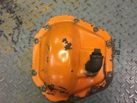
Note the street elbow installed in a Snowzilla diff cover by a previous owner. The concept is to raise the oil level inside the differential.
IMG_2975.jpg

Scars on one of Snowzilla’s carriers.

IMG_2997.jpg

Since we had the axles removed, we decided to copy a feature on the 1544. It has special spring U-bolt plates that have a tie-down loop incorporated and they make the process of securing a Tucker to a trailer a fair bit easier. We thought it was a clever design and Scott and I spent some time drawing it out on his CAD system (Scott did the drawing, I "helped"). Then we had a local vendor plasma cut them out of 1/2” steel plate before Scott added the bends with his hydraulic press. You might think the dimensions of the axle diameter and spring width were the same between the 1980 and 1986 machines, and thus we could merely copy the 1544’s plates. But you’d be wrong: both are different. We had enough made for both machines and got quotes from vendors for both plasma cutting and water jet cutting. Though the water jet process results in a nicer finished product, the cost was about double.

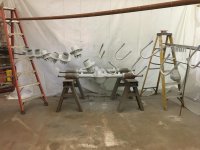
We erected a reusable, temporary paint booth and a mutual friend known as “The Evil Jester” painted a bunch of parts for us; first with a catalyzed epoxy primer and then he sprayed the top coat. They turned out surprisingly well, but there was a lot of work involved in prepping, hanging and masking all the individual parts. We believe if you’re going to go to all that work to take everything apart, it just doesn’t seem right to not continue the effort through the painting process, and that means using quality materials, too ($$$).

Some of the parts after primer was applied.
IMG_3110.jpg

I had to include a pic of “The Evil Jester”. Believe me the name is appropriate; he is exceptionally quick witted…
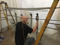
IMG_3115.jpg

These are the tie-down/U-bolt plates I mentioned.

IMG_3114.jpg

One of Snowzilla’s axles after painting and reassembly with new diff cover. Diff cover bolts are new stainless steel socket head cap screws with AN washers. Note the higher location of the fill plug.

IMG_3126.jpg

After axle shaft installation. New Stover nuts and lock washers.

IMG_3128.jpg

Unfortunately work, and progress, has come to a screeching halt. Summit County, Utah (where I live) issued a mandatory stay-at-home order, and that was followed up by both a voluntary state-wide order, and then another mandatory order in Salt Lake County, where Scott’s shop is.

My wife and I decided to “evacuate" to our second home in Southern Utah. There were (are) a number of maintenance projects we need to get done here so it seemed like the smart thing to do. BUT, it means no Snowzilla progress, and Scott and I have a LOT of work to do before Sun Valley 2021....

In the meantime I’m trying to think of parts that we will need, and ordering them so hopefully there will be fewer parts-related delays when the build resumes.

 
Basically TLBFT is saying it is his fault if Snowzilla isn't ready and Wbjr1 doesn't make it to the Seranade in 2021!
 
Basically TLBFT is saying it is his fault if Snowzilla isn't ready and Wbjr1 doesn't make it to the Seranade in 2021!

hmmmmmmmmm, hey Jr. you are either saying the Blackfoot tucker shops are never satisfied and will forever submitting change orders, thus no machine will ever be finished, or you are getting your excuses memorized and out in the public, so you have cover when you do not attend the 'great snow cat serenade'

this will fun to watch which bear pokes which bear more often.....:eatdrink:

PP,

Notwithstanding the deleterious effects of the stay-at-home orders on our Snowzilla completion deadline, the way I read WBJ1's post is he has admitted he won't have any excuse to miss Sun Valley 2021 if Snowzilla is completed....
 
Keep poking WBJ1…

BTW, Still waiting for you to commit to Sun Valley 2021. No political double-speak, or "weasel words”, if you prefer. Just a nice simple declaration….

But, don’t even think of trying to go incognito…it would never work. I think you'd be spotted in a second: if people didn’t recognize you immediately from your resemblance to an NFL fullback/ human steamroller, once you said three words - your accent would give you away!

Just think of the (revisionist history) fun you could have with Mikemikelle (at my expense).

Mike: “WBJ1, I can’t believe you “corked" that nice Tucker with a "cheater" motor….

WBJ1: "Mike, it wasn’t my idea. Blame BFT. It’s all his fault…I would have been perfectly happy with the stock 318.” (Except we all know you wouldn’t have been.)

But with enough beer... you might convince Mike… at least for that night.
 
secretly obtained from a source that wishes to remain anonymous, and confirmed, this is the power plant for Snowzilla, a Callaway V-16...and just delivered to the Zilla shops, Salt Lake City, Utah

uncorked! eh Mike

ain't no 318...
 

Attachments

  • callawayv16c.jpg
    callawayv16c.jpg
    58.3 KB · Views: 268
secretly obtained from a source that wishes to remain anonymous, and confirmed, this is the power plant for Snowzilla, a Callaway V-16...and just delivered to the Zilla shops, Salt Lake City, Utah

uncorked! eh Mike

ain't no 318...

:thumb:
 
secretly obtained from a source that wishes to remain anonymous, and confirmed, this is the power plant for Snowzilla, a Callaway V-16...and just delivered to the Zilla shops, Salt Lake City, Utah

uncorked! eh Mike

ain't no 318...and it answers the age old question, how much horsepower do you need to go 5 MPH

so cider tom, guess you had repowered your PT boat, originally, had Packard V-12's and three of them
 
yes, well I traded my boat to some guy named McHale for a mine he had. He got the craft, I got the shaft.
 
Callaway V-16 specs


  • 16 cylinder, 90° V-angle
, aluminum cylinder block with iron liners, aluminum cylinder heads
  • 4.0 liter displacement (243.6 cid), naturally aspirated
, electronic fuel injection
  • Bore: 75.50 mm (2.972″). Stroke: 55.75 mm (2.195″)
  • Compression Ratio: 11.5:1
  • Valvetrain: DOHC, 5 valves per cylinder, patented camshaft drive system
  • Maximum horsepower: 550 bhp @ 10,000 rpm (2.26 bhp/cid, 138 bhp/L)
  • Peak Torque: 340 lb-ft @ 8,500 rpm
  • Maximum engine speed: 10,500 rpm
  • Length: 926 mm (36.45″). Width: 540 mm (21.25″). Height to top of throttle body trumpets: 500 mm (19.70″)
  • Dry weight: 152 kg (334 lb)
  • Dry sump lubrication, triple plate 5.5″ diameter clutch, electronic coolant pump
 
That's what I'm talking about, a 10,000 rpm cat, sounding like a tweaked weedeater going through the forest.
 
Lots of itty-bitty parts to go wrong with one of those !!!!!:smileywac I guess simple,and reliable is not in the picture !!:smile:
 
So... an update after many months:

Due to governmental Covid-19 restrictions, my wife and I stayed away from both Summit County, Utah and SLC - "hiding out" in Southern Utah. Of course this also served to put the project further behind schedule. Here’s what Scott and I have been up to once work resumed on Snowzilla.

During my hiatus, Sno-Drifter very kindly called me and pointed out a flaw in the Tucker spring perch design, and he suggested how we might reinforce them. When I returned to Northern Utah Scott and I removed both axle assemblies from under Snowzilla to modify the spring perches per Sno-Drifter’s suggestions. In Snowzilla’s case, that meant ruining the relatively new black paint on the axle housings. But his suggestion also applied to Thundercat, and those axle housings had not been repainted after the E-Locker installation.

Here’s a pic of an unmodified Tucker spring perch on a Thundercat axle housing. Not a whole lot of strength there to resist axle wrap from engine torque...

IMG_0114.jpg

After modification. The side plates add a lot of additional strength. (Sno-Drifter deserves the credit for this modification!)

IMG_0117.jpg

The engine WBJ1 sent us had no exhaust manifolds, so we needed to source a set that would fit. eBay came through with some new LS series engine manifolds that looked like they would work. The key phrase in that sentence is “looked like”, because once we got them in hand the right side fit okay, but the left side had issues. Scott suggested we have the flanges that bolt to the cylinder head milled at an angle so the bottom of the manifold would protrude farther out from the engine, which would provide the clearance we needed. That change also required that the surfaces the exhaust manifold to cylinder head bolts contact be spot faced so they are parallel with the newly milled flanges. The OEM bolts are somewhat notorious for breaking, so we bought ARP 12 point stainless steel bolts, which are substantially stronger than the originals.

Here’s a pic of the left side manifold installed with those fancy (and expensive) 12 point ARP SS bolts.

IMG_0004.jpg

Another issue to be dealt with was the radiator. Some readers may recall the cooling issues Scott and I dealt with in the Thundercat project. Basically, I had contacted Griffin Thermal Products “Technical Support Department" and purchased the combination radiator and fan setup they recommended. Supposedly it cools 550 horsepower….except it doesn’t cool substantially less than that in a snowcat application (And I made a point to explain the snowcat's requirements in the conversation). We were unable to get that radiator to work adequately, and replaced it with a Ron Davis Racing radiator that actually does the job. But that meant we had an expensive radiator sitting around collecting dust, and WBJ1 wanted to try that in Snowzilla. Naturally there were complications....

The engine in Thundercat has the radiator inlet on the left and the outlet on the right, which also means the filler neck is on the right. There’s also a port for a heater hose return line on the right side. The L94 engine has both the inlet and outlet on the right side, there’s no heater hose port, but there is a steam port fitting for a line from the intake manifold, also on the right side. If the inlet and outlet are on the same side, one needs a “two pass radiator” as well. And of course the filler neck needs to be on the left which also means turning it around 180º so the overflow line is on the rear of the radiator. Scott spent some time carefully cutting out the various parts and relocating them, as well as adding a baffle to the right side tank to convert the radiator to a two pass configuration. It turned out quite well.

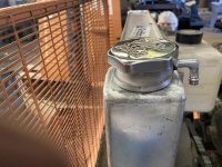
Here’s the filler neck after being cut off from the right side tank, the neck itself removed from the top of the tank, rotated 180º, and re-welded to the top of the tank.

IMG_0021.jpg

Newly installed on the opposite side.

IMG_0032.jpg

Here’s the relocated inlet port. If you look lower on the tank, you can see the baffle Scott welded into the tank.

IMG_0031.jpg

As always, we're farther along than the post indicates, but some forum members have been prodding me to update the thread so I thought it better to get at least something out there. More soon...


BFT,

Thanks for sharing, and also Sno Drifter, I'm about to go to powdercoat with my diffs but now I'll definitely want to make that mod to the spring perches first.
 
BFT,

Thanks for sharing, and also Sno Drifter, I'm about to go to powdercoat with my diffs but now I'll definitely want to make that mod to the spring perches first.

1BG,

I'm glad to have been of help, and very glad I didn't delay any longer in making the long overdue post!

I find Sno-Drifter to be a tremendous wealth of knowledge, wisdom and experience. When he kindly offers some thoughts... I listen...because I will definitely learn something.
 
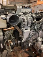
We also needed to come up with an air intake system which incorporates an air filter, a mass airflow sensor, some tubing and a mounting system. Of course all of this has to fit within the available space. We did this with Thundercat and and it was surprisingly time consuming, utilizing various lengths and angles of polished aluminum tubing, then welding several parts together. We were looking for a simpler solution with Snowzilla, but it needed to be functional and look good, too.

Top view

IMG_0085.jpg

Right side view (you can also see the new steam port fitting below the radiator inlet on top).

IMG_0084.jpg

Here’s a shot with the air filter removed showing the diagonal support bracket attached to the alternator mounting casting. (The mass air flow sensor is not bolted in position.)

IMG_0088.jpg

Snowzilla left the factory with the standard Tucker exhaust configuration which has a single muffler running along the cab’s right side A pillar. Especially after using the 1544 at Christmas time with a similar exhaust configuration, WBJ1 wanted a dual exhaust system out the rear. The factory exhaust routing has a good sized triangular section removed from the right side of the hood for the exhaust pipe. With a dual underfloor system leaving that gaping hole seemed amateurish. So Scott used a piece of aluminum salvaged from the rear door skin that we had replaced earlier, and bent a flange at the bottom to match the factory hood flange (adds rigidity to the bottom horizontal edge of the hood). Then he tig welded the filler panel in position.

Outside.

IMG_0063.jpg

Inside

IMG_0064.jpg

Procedurally, we don’t much care for Tucker’s practice of riveting raw aluminum to raw steel. This is guaranteed to result in galvanic corrosion, so we drill out all the existing rivets, separate the steel and aluminum parts, remove the rust and corrosion, then paint the contact areas before installing new stainless steel closed end rivets. More work, and the rivets are more expensive, too but the result is absolutely worth it.

Here the rivets that attach the hood sections to the center hinge have been drilled out and you can see the rust and galvanic corrosion where the hood has been pulled back and the hinge exposed.

IMG_0061.jpg

 
The paint on Snowzilla was original when I bought it, and it had not been repainted or even touched up, since it left the factory. It was badly faded, had many scratches in it and really needed some new paint. The modifications we did resulted in further damaging the paint in some areas, and the modifications themselves weren’t painted either. WBJ1 would have been fine getting it without being repainted at all. But this "has our name on it" and Scott and I take pride in our work. Sending it unpainted would look like the project was done by a couple of buffoons (like the youtube Tucker LS conversion videos).

To do a proper job it needed to be media blasted. Most fortunately there’s a couple of guys who have a blasting company less than 1/2 a mile from Scott’s shop. To get a better job, we stripped Snowzilla completely and loaded the various parts on a trailer.

Literally nothing else to remove. (The transfer case is on the shop floor.) The top of the frame is rusty. That’s because Tucker assembled the machine without any thought to rust mitigation, and painted it in an assembled state.


IMG_0093.jpg

Loaded on a trailer with some of the parts. Getting everything to the blaster required multiple trips.

IMG_0098.jpg

While Snowzilla was away at the blaster (sounds better than saying “getting blasted”), Scott and I spent some time working on the wiring. Snowzilla is getting a new instrument panel with new VDO gauges, including an added transmission temperature gauge, a new hour meter and all new Carling Contura XIV rocker switches replacing the stock Cole Hersee switches. Just like with Thundercat, the new switches have illumination for the switch function legend, and the switch function symbol.The legend lights up when the headlights are turned on, and the symbol lights up when the switch is in the on position. The heater fan has two positions, high and low speeds, and the symbol lights up when either of those is selected. Snowzilla has a four headlight grille and the lower headlights illuminate with the headlight switch in one of the on positions, and all four headlights illuminate in the other position, along with a blue LED High Beam indicator light. The function symbol lights up in either of the on positions.

Here's the new instrument panel with most of the new stuff installed. Despite having a ridiculous amount of LED lighting on Snowzilla, WBJ1 wanted additional locations for electrical system “growth”. Blank switch covers are installed in the holes for future additional switches. I have no idea what WBJ1 might be planning. Maybe some under-cat disco lighting and some "floor fog”? If you look at the large hole hole below and to the right of the tachometer you'll see it isn't round, but rather has two straight sides that are parallel. That hole is for the ignition switch, and the switch body has straight sides. Making the hole fit the switch body prevents the ignition switch from turning inside the hole, which it could do if the switch were installed in a round hole and someone turns the ignition key a little too forcefully.

IMG_0048.jpg

Here’s the backside showing some of the instrument panel wiring. The lighting system logic requires some extra wires. The switch function legend power comes from the headlight switch and the white wire with red spiral tracer is daisy-chained between the various switches and the gauges for them to light up as well. The black wire is a ground wire, and that too is daisy-chained. The gauges also need fused system power and that is the red wire. It gets connected to the ignition switch (which is yet to be installed). When you look at the photo it looks like it’s an easy thing to do. It’s not difficult, but cutting all the wires, stripping the insulation, crimping on the terminal ends and finally using a heat gun on the heat shrink tubing is surprisingly time consuming. Part of the concept is an easy-to-understand wiring logic and the other part is trying to do quality workmanship.

IMG_0149.jpg


If you would, please continue to add details of the electrical build out. Mine won't be that 'upscale', but I like looking at second (and third) ideas, thoughts & opinions. Mine can only go up from where it's at!
 

Attachments

  • Dash3.jpg
    Dash3.jpg
    102.8 KB · Views: 314
If you would, please continue to add details of the electrical build out. Mine won't be that 'upscale', but I like looking at second (and third) ideas, thoughts & opinions. Mine can only go up from where it's at!

Dave, I’ll try and do that when the project gets back to a wiring phase. My posts on this thread are always behind where we are “real time”. Right now we’re painting Snowzilla, and like so much else, it’s a slow process.

I can tell you the logic of the switch light system requires diodes to prevent back feeding on certain switches. Diodes are essentially check valves, which allow electrical current to flow in only one direction.

Some circuits also use relays. Electrical switches are rated for a given number of amps. The ones we are using are rated at 20 amps. If the item being powered draws more than 20 amps, one should install a relay to power the circuit. The switch is used to turn the relay on or off directing power to the circuit. Some electrical components are rated in amps and some in watts. The formulas to convert are simple. Volts x Amps = Watts or, knowing the watts and wanting to convert to amps, Watts / Volts = Amps. It’s a 12 volt system, so divide the number of watts by 12. Typical systems that use relays are powerful lights, horns, fuel pumps, electric cooling fans, etc. It’s very important to size individual wires for their electrical load (amps), and the length of the wire. The longer the wire, the greater the size (called gauge) it needs to be. But lower gauge numbers are larger diameter wires. There are easily found charts on the Internet that provide the correct wire sizing information.

Another item for consideration is how you want to connect wires. That is, what type of terminal ends do you want to use. There are a fair number of options and I’d suggest doing a little research to determine which type will best meet your needs. We decided to use the Delphi/Packard Weather Pack system. They require some special tools, but once you have the tools and the various parts involved you can make factory looking connections that are fairly weather resistant and yet come apart quite easily. Some automotive connections are downright miserable (the style used by Chrysler/Jeep seem to be the worst). The Weather Pack system offers lots of options. (I think the Deutsch system is probably better, but it’s also more expensive.)

One of my pet peeves is crappy electrical tape. Even 3M, which is generally known for making quality products, makes some (IMHO) lousy tapes. For Thundercat we bought an engine conversion wiring harness from Howell Engine Developments and the tape they use seems to work better than the stuff (including 3M) that I had been buying. I called Howell and asked to buy some tape from them. They obliged and sent several rolls of tape made by a company I had never even heard of, Plymouth Yongle.

Do you want to run your wires in split loom? If so, realize this too comes in different quality levels. Typically the cheap stuff melts at low temperatures and the better stuff is more temperature resistant. Ordering it online can mean significant minimum quantities. That’s frustrating when you only need a few feet of a particular size. I have found I can get shorter lengths at a NAPA store in SLC. The price per foot is higher, but who wants to buy 100’ if you need three feet? In my experience the better split loom has a stripe running down the outside of the split loom.

If you’re building a new harness from scratch and aren’t trying to replicate an existing harness, you’ll need to decide how individual circuits are powered. For example do you want the switch to be functional if the ignition switch is off (like the horn or headlights)? Or maybe you want it to work in accessory, or perhaps only in the on position.

Time spent thinking about and designing your wiring system is time well spent. Otherwise you’ll be taking it apart to revise it. Ask me how I know!
 
Top