Blackfoot Tucker
Well-known member
The blade system is made up of several different components; the blade, the A frame (which has a pivoting frame at the front), the axle mounted frame and the support frame, which is welded to the Tucker. We wanted to keep the overall project moving forward, and so put the A frame aside and concentrated next on the axle mounted frame. We'll get back to the A frame after the machined sleeve arrives.
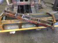
The factory axle mounted frame was constructed with 3” x 2” tubing with 5/16” wall thickness. That too will be lighter in that we used 1/4” wall tubing. Here’s an in-process photo of our axle mounted frame. The long, top and bottom parallel legs are 13” longer than the factory Tucker legs, and you’ll recall that was to position the hinge points for the A frame in front of the winch. Those parallel legs are one piece. For some reason Tucker made them from two pieces, and we don’t know why. The mounts where it bolts to the bottom of the axle are also being made by my friend back in Vermont, and they’ll be positioned by the back of the “X” frame members. If you look at that frame and think of the forces it has to deal with, it becomes apparent the welded and angled joint behind the “X” is the weak point. Tucker reinforced the frame by welding pieces of 1/4” steel plate on the top and bottom of that joint, overlapping the tube several inches in both directions. They also welded some 1/4” steel plate vertically across the inside of the angle for more reinforcement, and they added some 1 1/2” square tube underneath! Holy Overkill, Batman!
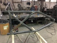
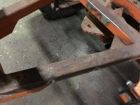
We thought of a simpler way, that we think looks better, takes less time and is more than strong enough. The other issue is the axle mounted frame is attached to the underside of the axle, so it hangs underneath and reduces ground clearance. The square tube reinforcement welded to the bottom of the outside frame members reduces that clearance even further. We took some 3” x 3” square tube and mitered the ends to intersect with the back of the “X” leg and the rear angled leg. Then its welded along all sides. We also added the square tube perpendicular to the long frame members in a similar fashion as Tucker did. (If you’re wondering why some pieces have a little surface rust while others don’t, it’s because steel is usually sold in specific lengths. We bought a 20’ stick of 3” x 2” square tube, and that wasn’t long enough. Scott had a remnant from another job (dimensionally identical) and we used part of that, rather than purchase another 20’ when we really wanted about 18”. Yes, one can buy shorter segments from a company such as Metals Supermarket, but the cost is painfully high.)
Another item to point out is the appearance of the welds. Scott has the capability, (equipment and skill) to do various types of welding processes. Typically he uses a MIG welder (Metal Inert Gas), but sometimes he uses stick (or arc). If it’s small detailed work, or a material like aluminum or stainless steel, he’ll use TIG (Tungsten Inert Gas). Yet another process is called dual shield. That uses both a flux core wire and a shielding gas, and that’s what Scott used on the A frame. Rectangular steel tube has rounded corners, rather than sharp, square corners. The thicker the tube, in terms of its wall thickness, the greater the radius of the corners. Thus 1/4” wall tubing has a larger gap at the radius intersection than does 3/16” thick tubing. That gap obviously has to be filled during the welding process.. Often Scott will make two passes; a “root” pass and a “cover" pass. With the A frame, Scott made the root pass with a MIG welder and the cover pass with his dual shield. The dual shield process is very strong and allows the welder to put down quite a bit of material quickly. As I mentioned, the wire has a flux core and that residue has to be removed after welding. But the weld itself looks a little different.
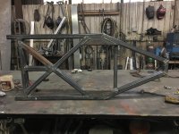
The factory axle mounted frame was constructed with 3” x 2” tubing with 5/16” wall thickness. That too will be lighter in that we used 1/4” wall tubing. Here’s an in-process photo of our axle mounted frame. The long, top and bottom parallel legs are 13” longer than the factory Tucker legs, and you’ll recall that was to position the hinge points for the A frame in front of the winch. Those parallel legs are one piece. For some reason Tucker made them from two pieces, and we don’t know why. The mounts where it bolts to the bottom of the axle are also being made by my friend back in Vermont, and they’ll be positioned by the back of the “X” frame members. If you look at that frame and think of the forces it has to deal with, it becomes apparent the welded and angled joint behind the “X” is the weak point. Tucker reinforced the frame by welding pieces of 1/4” steel plate on the top and bottom of that joint, overlapping the tube several inches in both directions. They also welded some 1/4” steel plate vertically across the inside of the angle for more reinforcement, and they added some 1 1/2” square tube underneath! Holy Overkill, Batman!

We thought of a simpler way, that we think looks better, takes less time and is more than strong enough. The other issue is the axle mounted frame is attached to the underside of the axle, so it hangs underneath and reduces ground clearance. The square tube reinforcement welded to the bottom of the outside frame members reduces that clearance even further. We took some 3” x 3” square tube and mitered the ends to intersect with the back of the “X” leg and the rear angled leg. Then its welded along all sides. We also added the square tube perpendicular to the long frame members in a similar fashion as Tucker did. (If you’re wondering why some pieces have a little surface rust while others don’t, it’s because steel is usually sold in specific lengths. We bought a 20’ stick of 3” x 2” square tube, and that wasn’t long enough. Scott had a remnant from another job (dimensionally identical) and we used part of that, rather than purchase another 20’ when we really wanted about 18”. Yes, one can buy shorter segments from a company such as Metals Supermarket, but the cost is painfully high.)
Another item to point out is the appearance of the welds. Scott has the capability, (equipment and skill) to do various types of welding processes. Typically he uses a MIG welder (Metal Inert Gas), but sometimes he uses stick (or arc). If it’s small detailed work, or a material like aluminum or stainless steel, he’ll use TIG (Tungsten Inert Gas). Yet another process is called dual shield. That uses both a flux core wire and a shielding gas, and that’s what Scott used on the A frame. Rectangular steel tube has rounded corners, rather than sharp, square corners. The thicker the tube, in terms of its wall thickness, the greater the radius of the corners. Thus 1/4” wall tubing has a larger gap at the radius intersection than does 3/16” thick tubing. That gap obviously has to be filled during the welding process.. Often Scott will make two passes; a “root” pass and a “cover" pass. With the A frame, Scott made the root pass with a MIG welder and the cover pass with his dual shield. The dual shield process is very strong and allows the welder to put down quite a bit of material quickly. As I mentioned, the wire has a flux core and that residue has to be removed after welding. But the weld itself looks a little different.


