• Please be sure to read the rules and adhere to them. Some banned members have complained that they are not spammers. But they spammed us. Some even tried to redirect our members to other forums. Duh. Be smart. Read the rules and adhere to them and we will all get along just fine. Cheers. :beer: Link to the rules: https://www.forumsforums.com/threads/forum-rules-info.2974/

"Snowzilla": A Comprehensive Tucker 1643 Project...

……. roger that....great... time is closing in … same boat here. I was just curious on the crossmember , where the front fifth wheel ''pivots''.... I want to clean up the ''mess'' on mine. and yours looked different , much better . a top view shot, and perhaps ..a left & right view...much appreciated...thx BFT...:thumbup::thumbup:

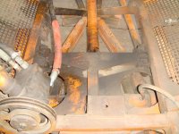
These three are pics of the setup on Thundercat, but it was identical on Snowzilla.

First shot is front to back. You can see an offset welded bracket with a single hole in it. That is where the 318 Industrial engine attaches with a single bolt. Looking slightly further back you can see two bolts on each side of the frame. These are also used to secure the bracket assembly the front fifth wheel plate rotates around.

DSC00932.jpg

This is of the same area, though from right to left. If you look closely you can see two bolts that go through a welded plate that is 90º to a frame cross member and welded to that cross member. The other side has a similar 90º bracket.

These six bolts two front and four further back comprise the means of securing that bracket to the Tucker frame.

DSC00935.jpg

We had removed the front fifth wheel plate (and the axle mounted blade frame) and you can see all six attachment points in this photo.

DSC01847.jpg
 
Hey Blackfoot ALSO collects F250's!! I am hoping to lighten his load of one of those as well down the road!!

WBJ1,

The word "collects" implies there is a "collection". I think the sum total of my F-250 parts would allow me to assemble two complete vehicles. While I suppose that could constitute a "collection", it would be a pretty meager one....
 
….... WOW … holy crap … great pics … glad I asked … damn , mine is nothing like yours... I can say ..cannibal...IZED,.. hmmmm … thx BFT...:thumbup:
 
WBJ1,

The word "collects" implies there is a "collection". I think the sum total of my F-250 parts would allow me to assemble two complete vehicles. While I suppose that could constitute a "collection", it would be a pretty meager one....

From Google
"How Many Items Make a Collection? There is no minimum number of items for a collection – in theory it is possible to have a collection containing only one item! Collections can also be very large and, typically, large collections will divided into a number of sub-collections."

How many Ford trucks do you own in total? Even the ones you would consider "parts rigs"? Sounds like you might ALSO have a "sub collection" of parts trucks!! :laugh3:
 
I'm trying to make more frequent thread updates.

After we had all the six-way blade frame parts that attach to the Tucker either welded or bolted on, it was time for a test fitting of the blade system components. Those were brought into the shop and assembled with steel pins (that we have yet to finish), and in some cases bolts, to complete the test fitting.

Here’s a front view.

IMG_2593.jpg

A side view. You can see the lift cylinder mount is just below the center of the hole in the winch mounting bracket, which is where the cable will be once the winch and roller fairlead are attached. Unless we wanted to raise the winch a whole lot higher and move the lift cylinder mount underneath (which we didn’t like the idea of), this seemed like the best compromise.

It looks like the blade is very far in front of the machine, perhaps too far. However, the 1600 series tracks extend about 51” in front of the center of the axle. In addition the tracks are 28” wide. If you draw that out on the concrete floor and then angle the blade fully to one side, that huge gap shrinks to about six inches. Realize too, track tension adjustment is at the front of 1600 series carriers on the front axle (and at the rear of the rear axle).

IMG_2595.jpg

It’s gratifying to be doing some test fitting, and though blasting and painting will have to be done before final assembly, it still feels good. Speaking of “blasting and painting”, Snowzilla will be getting a complete color change. I won’t reveal any details... but it will be very cool! I know, it’s somewhat mean to tease, but wbuffetjr1 (hereafter WBJ1) put me up to it…Honest.

We still need to weld the lifting eye (where the other end of the lift cylinder attaches) and we need to install a support rod from the fifth wheel plate to the axle mounted frame. We think Tucker's method can be improved upon fairly easily.

Here are some pics. See what you think.

DSC01155.jpg

A close up view (seems like an uninspired solution).

DSC01530.jpg

Stay tuned to see what we (probably Scott, again) come up with....

 
how about springs on both sides of the fifth wheel on the shaft from axle mount

PP,

Great minds think alike: I had the same idea! When I suggested it to Scott he sort of shrugged in a "Maybe, if we can't come up with a better idea" way. But his response and lack of enthusiam led me to believe he thought there was a better solution, though he has yet to disclose it.

I believe the purpose of that rod, and for lack of a better word, snubber, is to prevent, or reduce, the banging from play in the axle mounted frame's plastic block in the C-channel, especially if there is no blade attached.

I completely agree that springs, especially if the spring rate was dialed in, or perhaps a progressive rate spring, could work well. One limiting factor though is the amount of room above the fifth wheel plate for a coil spring.
 
I have a rig with that plow set up on it.

the seller told me that rod was only for loading the blade onto the machine. He cautioned me about tightening it too much. look at it as a positioning rod. When I hang the blade I drive into the poly socket and holder. rotate the rod up and in. hydraulically push down. (I skip this step and use a jack to lift it)

Spin the nut on.
put the caps on the axle tubes.
Raise the blade slightly

back or drive away and let it all get happy then push the blade down and tighten the caps on the bearing.

I do all the forementioned because that is what he told me to do and he pointed to the stack of washers and rubber like it was important as the limiter of sorts going over things.

He was an iron worker by trade.
He talked of the tucker frame as a flexible truss and that to work as designed everything needs to able to Give.

this machine has 19,000 miles on it and very little cracking that i am used to seeing. Ray may have been onto something.......

$.02 please
 
RS,

That’s an interesting concept. However, using that rod to help in installing the axle mounted frame sure seems like the hard way to do it. The nut on top of the rod is not really all that readily accessible. Using a floor jack, or even some type of lever and fulcrum, strike me as better options. Honestly too, with the plastic block at the rear of the axle mounted frame positioned in the C-channel, and the front of the frame resting on the ground, I’m not sure that rod would even reach the fifth wheel plate, let alone protrude far enough through it to use a nut to pull the rod up. But I’ve never tried...

Scott and I believe the purpose of the rod is to transfer some of the load to the fifth wheel plate. With the blade system installed, If the blade is resting on the ground and then one uses the cat’s hydraulics to raise the blade, the weight of the blade is then transferred to the front of the axle mounted frame. The axle mounted frame can rotate about the axle clamps that secure the frame to the axle, and with weight on the front end, the back end would want to raise up. But the rear of the axle mounted frame is restricted from doing so by the plastic block contained within the C-channel. If the length of the rod were adjusted correctly, it would limit how far down the front of the frame could travel and thus how much upward pressure is on the plastic block within the C-channel.

The square shaped pieces of rubber look like they’re cut from track belting and while that rubber can compress slightly, there really isn’t much "give" in it, rendering the rubber spacers pretty close to solid. In addition to merely stopping the front of the frame from dropping when lifting the blade, it also plays a role as the leaf springs flex, again limiting downward travel and sharing the load.

Using either upper and lower springs (as PP suggested) or an alternative means of shock absorption rather than an abrupt stop, seems like a better option to us. In addition, we want whatever solution we go with to be installed both above and below the fifth wheel plate. I'm told (I haven't ever done this) if you remove the blade and lift cylinder from the axle mounted frame and then drive the machine in that configuration there is an annoying banging sound, probably the play between the plastic block within the C-channel, but perhaps also when the rod setup hits the stop.

 
well, we got the answer as to why, the rod was to limit the drop of the frame assembly, behind the pivot/attachement point for the blade, per Jim Tucker, ( retired, former President of Tucker Sno-cat, lead designer/engineer ) he engineered that feature and explained its purpose to us....

"a stack of rubber squares was used to dampen the drop of the frame work and prevent the over rotation of the axle in relationship to the fifth wheel, because of the weight of the blade and frame work hanging on the axle"

my take away is, it is a very simple stop and do not over engineer it, springs would soften the action of the drop.
 
Last edited:
As the Snowzilla project progresses we made a major change in our project strategy. With Thundercat we made what we hoped would be all the modifications, and then took it out for testing. Unfortunately, testing revealed some issues that had to be resolved, and then more testing. Only then did we take it completely apart for blasting and painting. Scott and I think that’s the “right” way, but it also takes a fair bit longer. The majority of the modifications we’re doing to Snowzilla are similar to ones we made to Thundercat, so the original plan was to get the items done that require welding, and then remove the few things that have been installed and send it to be blasted and painted. Most everything else would be installed for the first time after painting. But as we were almost ready to send it to the blaster Scott wasn’t comfortable with all that hadn’t been done. He wanted to spend more time and get more systems preliminarily installed. It’s more time consuming, and making that change will kill our goal of a Christmas 2019 ready time, but we think the finished product will be better, and so the plan was changed. Unfortunately that means Snowzilla will be “mothballed” for awhile. WBJ1 needs a snowcat to use at Christmas time, and we need to make certain we have one available for him. The 1986 1544 will be the loaner ‘cat, but it needs some repairs and maintenance before it’s ready for that role. My wife has knee replacement surgery scheduled for early November and I’ll be her primary caregiver once she gets home from the hospital. That will severely restrict the amount of time we have for snowcat projects, so we need to get after the 1544 to ensure readiness at Christmas.

A few posts ago I mentioned I typically write stuff up after the fact as time permits and then make a thread post. That means we’re usually working on something else when a post is made. "Real time”, we're waiting on some parts to finish the hydraulic pump mounting bracket, which also incorporates a belt tensioner. We intend to finish that sub-project before we put Snowzilla on hold. We've also been doing some preliminary work on the wiring system which I’ll explain below. Sadly, no pics in this post.

There are quite a large number of changes to Snowzilla's electrical system; some wires get removed (precious few) and a whole bunch get added. We’re installing a new instrument panel, adding a bunch of additional switches (with four extra switch cut outs for additional future system "growth"). We’re also changing the switch style from the factory Cole Hersee rocker switches, adding a transmission temperature gauge, and it was recently decided to change the existing gauges, too. A nice, clean, logical and professional looking wiring system is the goal. To achieve that, one really needs to spend the time researching the various systems and accessories and determining their respective electrical loads. You also need to measure the length of each wire from the accessory to the power source. That then allows one to select the proper gauge wire. The electrical loads must be compared to the switch amperage rating to see what systems can be controlled with switches, and what systems need relays, and then make a list of what wiring supplies will be needed. That also involves deciding what color wires will serve each function as part of a color-coded schematic. Time spent thinking and organizing is time well spent, as it hopefully prevents having to go back and add stuff that you forgot. (Been there-done that (more than once).)

It can be difficult to find all kinds of different colored wires, and in various gauges. There are only so many solid colors, so pretty soon you start using wires with stripes. These are actually called “tracers”, and one can get tracers in various colors, which really opens up the number of options. Tracers can be straight or spiral, and you can have multiple tracers on a single wire. For example, a white wire with red and blue spiral tracers. From experience, we prefer spiral tracers as whatever angle you look at the wire, you will see the tracer(s) (with a straight tracer pattern that’s not necessarily the case).

As you know, Snowzilla has been in the works for quite some time. A few years ago WBJ1 and I discussed vehicle lighting, and various options for different light functions. Shortly thereafter shipping boxes (plural) started arriving with lights. Knowing we didn’t need them for awhile, Scott and I just stacked the various unopened boxes in a safe, out of the way place. Some of the boxes seemed quite large but I chalked that up to the lights being well protected with lots of packing material. Well, to calculate the wiring needs for these lights, we had to dust off the boxes and open ‘em up to see what was inside, and what the electrical requirements are, so we could order the right supplies.

Far be it for me to suggest WBJ1 went overboard, but Scott and I were quite literally incredulous at what we discovered. The image of WBJ1 ordering lights seemed analogous to that of a young child going to a candy store with Grandma who says “Get whatever you want, I’m buying”. Mind you, all of these are LED lights, not incandescent lights. I don’t want to divulge any specific details at this point, but we added up the electrical requirements of the various LED lights…. OMG!

I’ll pause for a moment and say these lights were bought back when the plan was (or maybe I should rephrase that and say, “when Scott and I thought the plan was”) to use the stock Tucker Chrysler 318 Industrial engine. That engine has a 41 amp alternator, and that number is somewhat ironic because if all the lights are turned on at the same time, the amperage needed to power the abundance of LED lights being installed on Snowzilla is literally twice that! Yup, no kidding, 82.33 amps…just for the lights! I won’t mention the total wattage, but the mathematical formula is volts x amps = watts. It’s a 12 volt system. 12 times 82 = YGTBSM!

I’ll again point out these are LED lights... and they put out roughly FIVE times more light per watt than incandescent lights. I’m not up on the latest conventions of social media but #overkill seems about right….

Picture this scenario:

It’s a clear, dark moonless night. A FedEx MD-11 wide-body cargo plane is enroute from the west coast to Memphis for the evening sort, and is presently over Western Colorado...

FedEx 123: “Denver Center, FedEx one twenty three, do you have time for a question?”

Denver ARTCC (Air Route Traffic Control Center): “Sure thing FedEx one twenty three. Go ahead with your question.”

FedEx 123: “Denver, there’s a really bright, white light in the middle of nowhere at our 1 o’clock position for about 10 miles. Any idea what that is?”

Denver ARTCC: “Roger Fedex one twenty three, we had some inquiries about that earlier. The Montrose County Sheriff’s Department said it’s some knucklehead with a snowcat apparently trying to light up the whole county.”

FedEx 123: “Thanks Denver. If that’s his goal, he’s doing a good job.”
 
1. hope mrs Blackfoot has a successful surgery and recovery

2. hmmmm, change oders......

3. thinking a onboard Honda generator might the best solution for the lighting up the entire
forest....thus creating a light-out
 
In my defense, two things.....

One, I don't plan on turning on all the lights at once ALL the time!! Haha

Two, Blackfoot for some reasons prefers to navigate via candle light. Whenever we finally get to go catting together I figure I will have to have enough lights for both of us!!

Since there were no pics posted. I will post one. This is one of his actual headlights!

mtFPAEO.jpg


pretty sure you will need a stand alone Honda generator to handle your amazing light show, and darn sure the space station will be able to see you.

Houston, Houston, Houston, what the H#ll is going on in Colorado?
 
Don't listen to them. Light it up.

https://www.youtube.com/watch?v=A5hYZxX2MHU

LED light range is poor, but the quantity of light is fine for our snow cat pace.
I like watching this video when ( like motor oil conversations ) the lighting opinions opinions leak out.

Most are LED Bars. some are incandescent, Only one had oil lamps or was it carbon arc.?

two alternators will handle it, and be able to weld as well..... More HP!
 

Attachments

  • 20191008_154827.jpg
    20191008_154827.jpg
    75.5 KB · Views: 313
The biggest thing is the reflective property of the snow in the air. And even when it's crystal clear out, there is still moisture to glitter & reflect. It tires out the eyes after a while . . .
 
Looks like good ol’ Blackfoot is taking some shots…That’s okay; fire away!


Red Squirrel, Thanks for the video link. That was nice.

PP, Thanks for the kind wishes regarding Mrs. Blackfoot’s upcoming surgery. This will be her left knee, and her right knee replacement did not go well. The first prosthesis (a press-fit type) had to be removed and a second prosthesis (this time a cement-in style) was installed. Of course that was literally like starting from scratch; with twice the recovery time and twice the physical therapy. It’s fair to say we're concerned. What’s sad is she was a really great skier, and enjoyed it immensely. Her skiing days are probably over, despite the new knees.

Snowzilla progress has just about come to a stop. I had ordered some parts we needed to complete the hydraulic pump bracket (we typically buy parts from rockauto.com). They arrived and we finished the bracket fabrication last night. I brought the bracket home for some clean-up, media blasting and painting. It’s ready to bolt on to the engine and then the hydraulic pump, new pulley, new belt tensioner and new serpentine belt get installed. Snowzilla’s grille and hood have been reinstalled for temporary storage.

In my last post I mentioned we are changing the switch style from the stock Tucker Cole Hersee rocker switches. Just as with Thundercat, the new switches have a text and a graphic describing their function, and the same lighting logic will be followed: turn on the headlights and all the switch texts light up (so you know what each switch does). Then as switches are turned on individually the graphics light up. The new switches have been ordered and should arrive next week. Due to the plethora of LED lights we needed to have some of the switch rocker covers made up specially to reflect the switch functions and/or the switch graphics on Snowzilla. I think followers of this thread will enjoy the finished product of the new instrument panel, though it will be awhile before we’re back on Snowzilla again.

While waiting for the new serpentine belts and the belt tensioner to arrive, we started working on the “loaner cat” for WBJ1’s use at Christmas time. That project will have its own thread titled Tucker 1544 IRAN Project. Expect that thread to start soon...
 
Don't listen to them. Light it up.

https://www.youtube.com/watch?v=A5hYZxX2MHU

LED light range is poor, but the quantity of light is fine for our snow cat pace.
I like watching this video when ( like motor oil conversations ) the lighting opinions opinions leak out.

Most are LED Bars. some are incandescent, Only one had oil lamps or was it carbon arc.?

two alternators will handle it, and be able to weld as well..... More HP!

may be for yours but my lightfoot will run circles around the tuckers, thiokols and snowtracs. Forgot the krusty crowd but I hear there is no evidence they actually move under their own power.
 
Last edited:
The biggest thing is the reflective property of the snow in the air. And even when it's crystal clear out, there is still moisture to glitter & reflect. It tires out the eyes after a while . . .


Amber lights like in the fog a better option?
 
Don't listen to them. Light it up.

https://www.youtube.com/watch?v=A5hYZxX2MHU

LED light range is poor, but the quantity of light is fine for our snow cat pace.
I like watching this video when ( like motor oil conversations ) the lighting opinions opinions leak out.

Most are LED Bars. some are incandescent, Only one had oil lamps or was it carbon arc.?

two alternators will handle it, and be able to weld as well..... More HP!

Just another thought. We just put some amber strobes that mount under the bumper of a new foreman's pickup. They are about 2"x6", led commercial duty and rated for 9-30 volts. 12 volt system on the pickup of course, but also added the same lights to a piece of equipment with 24 volt system. I swear they are twice as bright running on 24v.
 
I thought I’d add some photos of the hydraulic pump installation and serpentine belt routings after everything was installed. Below is a diagram of the factory belt setup on the GM L94 6.2L engine.

0996b43f8022f5a5.gif


Since we were not using the power steering pump, it was removed. We also took an angle grinder with a cutoff wheel and whittled away at the large aluminum casting that comprises the mounting bracket for the alternator, idler pulley, and the power steering pump. With the power steering pump removed, we needed to reconfigure the serpentine belt routing and purchase a new belt of the correct length.

The above diagram also shows the A/C compressor and its drive belt. I previously mentioned we mounted the hydraulic pump in roughly the same position. I also mentioned we used a different harmonic balancer that allowed us to mount an auxiliary pulley to the balancer. The new harmonic balancer is smaller in diameter than the original balancer. Because the new balancer under drives the alternator, a smaller alternator pulley was installed to maintain the correct factory crankshaft and alternator RPM relationship. (Especially important in lieu of all the LED lights being installed!)

Here’s a photo of the two alternator pulleys.

IMG_2621.jpg

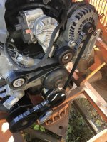
Here’s everything installed. Not a great picture of the modified aluminum bracket casting, but you can see the new serpentine belt routing.

IMG_2651.jpg
(Note: For some reason when I uploaded the photo it rotated 90º CCW. I don't know how to fix/prevent that.)

Here’s photo showing the hydraulic pump mounted to the engine, as well as the tensioner, and auxiliary pulley.

IMG_2649.jpg

A front view.

IMG_2652.jpg

Though this setup looks pretty simple, I can assure you there was plenty of head scratching and thought put into the design and fabrication. It turned out very well and the pump and tensioner are very solidly mounted.

Snowzilla is now in temporary storage as we work on the loaner ‘cat (1986 1544) to get it ready for Christmas usage by WBJ1. Once that’s done, Scott and I will finish assembling Thundercat so we can actually use it this winter. But, I’m quite sure we're going to make some additional modifications, which unfortunately means taking some backwards steps before moving forward.
 
WOW! It looks like you guys have once again out done yourselves!! It looks fantastic! Elegant solutions have a way of making things look simple, IMO.
 
all fixed...

thought I would let you know, winter is coming and fast......ask the squirrel, all the nuts have been gathered
 

Attachments

  • fullsizeoutput_2de.jpeg
    fullsizeoutput_2de.jpeg
    294 KB · Views: 243
all fixed...

thought I would let you know, winter is coming and fast......ask the squirrel, all the nuts have been gathered

PP, Thanks for fixing the sideways photo. For future reference, how do you do that?

Winter is coming all too fast. We have a LOT of work to do... and not all that much time to do it.
 
Top