• Please be sure to read the rules and adhere to them. Some banned members have complained that they are not spammers. But they spammed us. Some even tried to redirect our members to other forums. Duh. Be smart. Read the rules and adhere to them and we will all get along just fine. Cheers. :beer: Link to the rules: https://www.forumsforums.com/threads/forum-rules-info.2974/

Astro van cat conversion

Parts going back on...This time with grease where it needs to be.....
Bolting things down with nylock nuts too....

Some parts were a tad sticky yet....gonna let the paint set more......

Getting the grease adjuster assembly in was far easier than I was thinking it would be.

With the new seals in the cylinder and the parts all together the beast slid down the frame rail easily.....

Fastened the grease manifold in first then stuck the 3/4" bolt through the frame and the rear of the cylinder... (The grease hose is a tiny bit long...so the little manifold needs to be bolted in with the two 1/4" bolts first....then the cylinder shoved back to get the 3/4" bolt though the back head of the cylinder)
An interesting thing came up when assembling the grease cylinder.

The original cylinder barrel (Rusted to rat crap) had a spiral ring installed in the end to keep the piston from over traveling..
The Original piston seals were badly damaged (Lip on the inner edge was cut and mutilated)
Getting the piston in past the snap ring groove takes a bit of finesse using a thin feeler gauge as a tool to gently "Shoehorn" the seal past the groove...
I did not have a tool to cut the ring groove in the barrel....Soooooooo...I drilled 4 evenly spaced 3/16" holes around the barrel end and tapped in 4 roll pins ....These will secure the piston from over travel......

The last crew to have these cylinders out likely used a 5 pound club and just hammered the piston into the cylinder.....thus the damaged seals.
The LH cylinder seal had a huge chunk cut in the seal lip.....The frame had about 10 pounds of grease in it that had leaked out past the seal.......No doubt making a stable track adjustment impossible......
RH side was just rusted up beyond use......

And on we go.


Removed the Zerk and the adjuster assembly slides in and out very nice....

Assembled the inner adjuster and it too operates quite nice....

Inner is a 5/8" coarse threaded unit.....

The Air bag arm is nearly ready to go back on.....brackets painted and still a tad tacky.

I still need to redo the sketch for the bag arm so we can make the LH part the same..... This area had a few revisions as it was coming together....so we need to make the other one the same......IF I WAS TO DO IT OVER....There would be some changes to the design to make it easier to build.....but at this juncture it will remain as is.....

One big change I would like to have been able to do is to have access to a key way broach and made the hub that goes onto the axle at the bag arm a custom part to my specs instead of adapting parts.

This time through... the red bushings are going to get the Super Lube slathered all over them as they go back in.
Same with the axle. Urethane likes to be lubed up to stop squeaks and other unpleasant operation..... The Energy brand bushings for trucks have a silicone lube available......
The custom bushings on the cat are the same material 95 durometer urethane....


That super lube is supposed to be WATER PROOF.....A good thing... and it sticks really well....USE RUBBER GLOVES

Be cool to get the axle shaft hard chromed.....It would last forever .....and not rust....even galv would be good...

It's coming together.....
 

Attachments

  • RH LAST ASSEMBLY4.jpg
    RH LAST ASSEMBLY4.jpg
    433.4 KB · Views: 76
  • RH LAST ASSEMBLY3.jpg
    RH LAST ASSEMBLY3.jpg
    407.4 KB · Views: 72
  • RH LAST ASSEMBLY2.jpg
    RH LAST ASSEMBLY2.jpg
    461.4 KB · Views: 88
  • RH LAST ASSEMBLY1.jpg
    RH LAST ASSEMBLY1.jpg
    478.6 KB · Views: 77
Last edited:
Well now....the time we have been waiting for has come.....The RH front axle is complete (Just need to install the upper track safety skid on the inner adjust assembly.....I need to cut the UHMW then bolt it on.......Can be done later)

All painted up, greased well with the silicone/PTFE grease.
The pics show a lot of details.
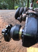
The inner end of the axle is covered with a slip on tubular cover that is held in place with a 1/2" bolt...This also shoves the air bag arm against the cross bolt in the shaft.....Shaft is keyed to the air bag arm....

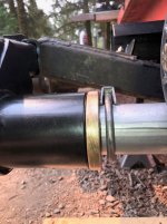
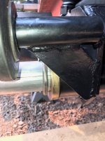
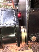
The various Brass thrust washers.....Inner ones are 1/2" thick and the outer one by the spindle casting is a touch over 2" (Machined to place the hub flange in line with the other hubs) The thrust washer closest to the bag arm has a notch cut in the inner bore to allow the keyed axle to be slid back far enough so the air bag arm can be slipped between the inner adjuster frame and the tub....then slide the axle towards the tub and through the bag arm.....Sort of like a Chinese puzzle....once things all line up....it goes right together.....

The inner split steel tube spacer with retaining clamps and the inner brass thrust washers

The upper bump stop bracket (Also has the exhaust flange access cover on it too)
The air bag and related parts.

All the Nylock nuts are on the bolts where needed.
The track guide safety "Goat wheel"

The air bag lower perch location adjuster.....Allows keeping the air bag lower perch where it needs to be no matter where the track adjuster winds up.

The inner track adjuster......

The grease cylinder jacks the track to tighten it and the inner adjuster will keep the axle parallel to the frame.....
Probably clamp a short chunk of hose over the adjuster threads to protect them.

At present the threads are greased well.....
 

Attachments

  • RH COMPLETE8.jpg
    RH COMPLETE8.jpg
    375.6 KB · Views: 66
  • RH COMPLETE7.jpg
    RH COMPLETE7.jpg
    284.7 KB · Views: 70
  • RH COMPLETE6.jpg
    RH COMPLETE6.jpg
    283.2 KB · Views: 77
  • RH COMPLETE5.jpg
    RH COMPLETE5.jpg
    344 KB · Views: 65
  • RH COMPLETE4.jpg
    RH COMPLETE4.jpg
    373.9 KB · Views: 71
  • RH COMPLETE3.jpg
    RH COMPLETE3.jpg
    333.5 KB · Views: 66
  • RH COMPLETE2.jpg
    RH COMPLETE2.jpg
    456.7 KB · Views: 73
  • RH COMPLETE1.jpg
    RH COMPLETE1.jpg
    450.2 KB · Views: 68
Last edited:
  • Like
Reactions: PJL
OFF TO A GOOD START BACK ON THE LH SIDE.

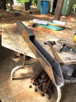
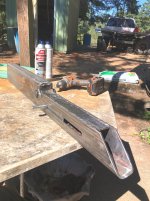
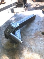
Grabbed the piece of box tube for the LH air bag arm.

On the right side I laid it out and cut the notch in the tube with the torch.....Arrrrrrgh....Just not as nice as I wanted....

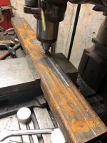
So on this one I laid out the part and tossed that bad noy in the mill and cut the tube with an end mill.

I buy used tooling by the BOX FULL cheap off ebay.....Grabbed a 1/4" cobalt 4 flute end mill and put it to work....

Took a little longer than the torch cut....But oooooooh sooooo much nicer result.

Pics.

The arm tube in the mill.....
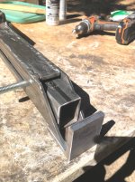
The arm tube cut..
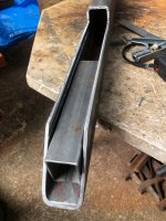
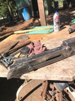
Arm with the bag perch locator slide tube sitting inside the arm.....

Next we will cut the filler plate to weld into the arm.

Then layout and drill the end holes for the slot in the arm.....followed by a trip back to the mill to slot the arm on both sides.

The little perch locator tube gets drilled 17/32" on center and then gets a plate welded into one end for the thread rod to screw in.....

Going to build this arm in a slightly different order than before.....

Be cleaner and a tad more accurate....also be a nicer finished part too.....

But when you are "Imagineering" as you go....there is usually room for improvement the second time around....

Once the arm is finish machined then the hub assembly will get fabricated ....followed by locating the axle in the adjuster assemblies and then welding the hub into the arm.

The hubs keyway must be located on the axle with the spindle at the same lower position as it's RH side mate.

Then the axle shaft gets marked and the key way cut in the axle shaft......

Axle then gets a 1/2" hole drilled through the hub and then the shaft too.

The entire procedure should go much quicker than the RH part did.....WE KNOW WHAT TO MAKE AND HOW TO DO IT....

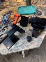
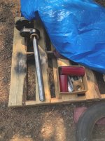
The LH axle and spindle casting are pressed together and ready to be welded.....

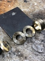
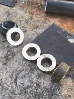
The brass thrust washers are as follows.

One center one is completed, the other center one is cut...just needs finish machining to thickness and bore then center to size.
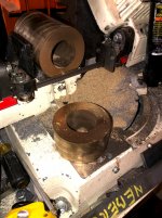
The thick outer end brass has to be cut yet....and then machined.

The inside thrust washer needs to be cut, machined to size and the clearance notch milled in it for the Key to slide through.

Axle needs to have a hole drilled and tapped in the inner end for the retainer cap to bolt too..

Sadly the shaft is too long to fit in the lathe.....gotta drill that SOB by hand......Arrrrrrgh..

With the inner track adjuster frame finished and bolted to the cat frame, as well as the outer adjuster modified.....we are off to a very good start.

The inner adjuster slider needs to have the bushing tube located and welded.....It is still loose in the assembly......

The original outer track adjuster is complete now and ready to clean up, paint and get the grease cylinder back together and then that entire assembly can go back onto the cat.

If the weather will stop trying to fry my azz I can get this stuff done fairly quick..

Weather dudes are talking 100's F next week by Wed... YUCK

I prefer 60 F and a breeze (Accept when I need to weld)


Gonna be nice to have the front axle mods finished.......

Then we will see where we go.....
 

Attachments

  • LH AIR BAG ARM2.jpg
    LH AIR BAG ARM2.jpg
    471.4 KB · Views: 71
  • LH AIR BAG ARM1.jpg
    LH AIR BAG ARM1.jpg
    296.7 KB · Views: 65
  • LH AIR BAG ARM3.jpg
    LH AIR BAG ARM3.jpg
    520.3 KB · Views: 74
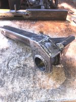
Got the top pieces of the arm welded in today. (The notch filler plates)
Been feeling really yucky since Early Saturday......Getting better this afternoon.....so maybe tomorrow I can get more done.

Last night I was feeling like this might be the stinking Virus.....But its on the way out now.....

Been shopping around for a good cam for the FrankenMouse 406

I want to use the Vortec heads as they are .....So valve lift needs to be kept pretty tame......The heads are in great shape and pretty much gonna be a clean and bolt on....EXCEPT drilling the "Steam holes" between the cylinders...(400 has adjoining cylinder walls that do not flow water between them)

Will need to set the heads up in the mill and CAREFULLY drill the 6 holes in each head.

I found a couple cams that look like a winner.

One is the old 327/350 hp factory cam.....447" lift and 222 degree duration.
The big inches will cover much of the rumpiness of this cam.....

I have used this cam in a 400 years ago.....and it is just rumpy enough to give away that there might be something mean under the hood.......

I have never built a 400 with Vortec heads though......The vortecs will bump the compression ratio to about 9:1 or a tad more with the stock type pistons.....

But.....big power is not really the goal.....The original 391 Ford that came in this cat were about 250 hp and about 370 lbs of torque at 2000 RPM

The little mouse 406 will have zero trouble making all of 375 hp and 400 lbs of torque.....MAYBE MORE......But too much power will not do much ...except break chit......

I could go all out "BALLS TO THE WALL" but it will not really be useful and as mentioned.....BREAK THINGS....

Decent power and a nice Thumpy idle will be Purrrrrrrfect....

We shall see what shakes....

I have saved the stock rocker arms from the Vortec heads and will need to replace the push rods (We need Gen One parts to use with the flat tappet hydraulic cam)

Trying to use as much stuff that came with the engines as possible.....

Currently that includes the 400 block (Now 406)
Factory crank and rods....New +.030 pistons
Vortec heads
Vortec center bolt valve covers
Stock 400 timing cover
6 quart road race gated pan (This will sit nice in the 2100 belly)
Stock Vortec mini starter
Serpentine front drive off the Vortec...
Late style alternator.....
1995 5.7 exhaust manifiolds (To get the damned thing to fit in the 2100 tub)

Vortec style aluminum intake that will accept the 750 cfm Quadrajet carb.

Gonna be fun.......>
 
Got a bit more work done on the LH side.

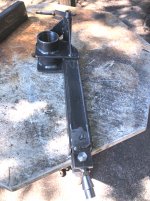
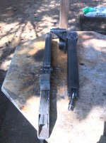
Air bag arm welded up and the slot machined in for the bag perch position adjuster.....

The miserable hot weather is back again....ARRRRRRRGH
Getting too hot outside to beat on this stuff.

Next the inner tube gets the end piece welded in and the hole for the adjuster rod put in......

Thinking about making this side a tad different....We will see.....

Should keep the parts the same......
 

Attachments

  • LH AIR BAG ARM6.jpg
    LH AIR BAG ARM6.jpg
    362.4 KB · Views: 63
  • LH AIR BAG ARM5.jpg
    LH AIR BAG ARM5.jpg
    354.8 KB · Views: 68
  • LH AIR BAG ARM4.jpg
    LH AIR BAG ARM4.jpg
    414.6 KB · Views: 69
Out at the Buttcrack of dawn when it was cool (Relative term)
Grabbed up the LH inner track adjuster and tossed it in the inner slide tube.....

Checked the measurements between the inner and outer adjusters and compared them to the RH side parts.

Very close......The inner adjuster was just tacked together... Set the inner bushing tube to it's sweet spot and tacked it up well....

Got the assembly off the cat and on the table.....Welded the best up.

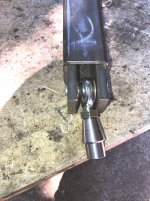
Grabbed the pieces that go in the back end where the heim joint goes and fit them up....

Drilled the 1-1/8" holes in the adjuster to plug weld the plates that the heim joint goes between......

Drilled the 5/8" hole for the pin that goes through the heim joint (5/8" bolt cut and machined to fit in and slip inside the inner tube assembly.

All spiffy now.

Just too hot out there in the afternoon sun.....sitting at 90 F now....ARRRRRRRGH

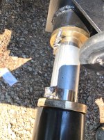
I was looking at the exhaust clamps I used on the RH side to hold the center spacer tube halves together.....

Just a bit tacky.....Decided to go with some stainless steel T bolt clamps.....

Far nicer looking....

A little tab with a couple holes in it can fasten to the thread on the clamp and to a hole in the Goat Wheel support to keep the clamps facing up and not down into harms way.....

Tomorrow will either be used to fab the air bag bracket up or maybe machine the adjuster nut units for the inner track adjuster or the air bag lower perch adjuster.

Will see wasssssup tomorrow when it gets here...

Now that the RH side is complete.....LH side can go quick......

Be nice to get the front axles done....
 

Attachments

  • LH INNER TRACK ADJUSTER FINISH5.jpg
    LH INNER TRACK ADJUSTER FINISH5.jpg
    422 KB · Views: 92
  • LH INNER TRACK ADJUSTER FINISH4.jpg
    LH INNER TRACK ADJUSTER FINISH4.jpg
    397.7 KB · Views: 108
  • LH INNER TRACK ADJUSTER FINISH3.jpg
    LH INNER TRACK ADJUSTER FINISH3.jpg
    398.5 KB · Views: 104
  • LH INNER TRACK ADJUSTER FINISH2.jpg
    LH INNER TRACK ADJUSTER FINISH2.jpg
    464.4 KB · Views: 103
  • LH INNER TRACK ADJUSTER FINISH1.jpg
    LH INNER TRACK ADJUSTER FINISH1.jpg
    419.8 KB · Views: 108
  • RH AXLE CENTER SPACER CLAMPS.jpg
    RH AXLE CENTER SPACER CLAMPS.jpg
    343.8 KB · Views: 96
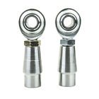
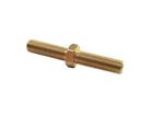
I just found a RH/LH threaded adjust stud that I can screw the LH heim joint to and use the thing to turn the threaded bung down in the lathe a bit.
I tried to scare up some 5/8" 18 LH thread rod.....Waaaaaaaaaaaay too $$$$$$$$$$$$$$$$....must be gold.....
Need to machine a little adapter to allow the 5/8" coarse thread to screw into the heim joint for the inner track adjuster.

I bought a set of RH and LH heim joints ....simply because they were available as a set cheaper than buying single units (Both RH)

Having a LH thread will make zero difference.....The heim joint simply makes the connection easier and allows the track adjuster tube to wobble around a bit in the slide tube and not bind up....

The pics show the heim joints threaded into the "Bung" These are designed for a .120" wall tube....I grab the bung in the lathe and turn the back end down to about .800" and then slip it into my custom adapter..(Adpter is drilled and tapped to accept 5/8" 11 coarse threaded rod in the one end and the opposite end allows the .800" part of the "Bung" to slide in and be welded.

The double ended bolt is RH/LH and will work sweet to thread into the "LH bung" and allow it to be grabbed in the chuck of the lathe....
Little bolt was $8.00

A great little special tool should the need ever arise to make any new heim joint adapters....
 

Attachments

  • s-l140 (1).jpg
    s-l140 (1).jpg
    4.1 KB · Views: 60
  • s-l140.jpg
    s-l140.jpg
    1.7 KB · Views: 60
Last edited:
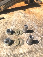
Again

Got out early while it was relatively cool outside.
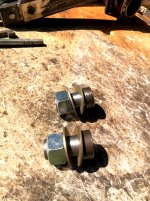
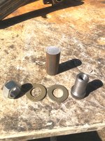
Cut the materials and machined up the adjuster nut assemblies for the inner track adjuster and the air bag lower perch adjuster.

Same part....Just the little bracket is thicker on the track adjuster .... so the nut gets welded on in a slightly different spot on the tube is all.

The track adjuster assembly is easily replaced due to the amount of pressure that can be on the nut.....The Bag perch adjuster takes little to no stress....so it is installed and welded.....( A new one could be fitted by grinding off the weld and replacing the nut assembly and welding it....

The RH units started out different....but I decided to change the design in favor of something far less complicated.....

Nice to be where it's cool now and sucking on a cup of coffee......

Today is supposed to be the hottest day of this heat event....ARRRRRRRRGH...

But work got done....that's the important part...

Maybe tomorrow the air bag mount can get finished up....

Plate is marked for the bolt holes....Need to drill them and fit the plate into the top bag mount....THEN WELD....

I want to get all the parts made before I start the assembly.....

Since the assembly is identical to the RH side....Getting it together should be a snap.......
 

Attachments

  • LH ADJUST NUT ASSEMBLIES2.jpg
    LH ADJUST NUT ASSEMBLIES2.jpg
    604.1 KB · Views: 105
  • LH ADJUSTER NUT ASSEMBLIES3.jpg
    LH ADJUSTER NUT ASSEMBLIES3.jpg
    649.5 KB · Views: 92
  • LH ADJUSTER NUT ASSEMBLIES1.jpg
    LH ADJUSTER NUT ASSEMBLIES1.jpg
    623.7 KB · Views: 87
  • Like
Reactions: PJL
Not much shaking today....

Was looking at the back of the cat this morning and the rubber mounting biscuits for the OC-12 were laying in the ledge of the tub.....

Thinking about this area and decided to snoop about a bit and see what can be scrounged up to build new mounts ......
What is there appears to be fairly close to what is shown in the parts book I have....

Thinking about going with Urethane for the biscuits.....
I can get a round 90 durometer round bar of Red urethane about 2 feet long pretty affordable....

Easy to cut this stuff in the band saw.....
A brad point drill will put the holes in easy enough.

The steel sleeve that goes through the biscuits is a bastard size......11/16" OD and uses 7/16" bolts

I can get 11/16" DOM tube (Drawn over mandrel) with a .495" ID This is really close to the rusty POS that came out.....

The frame has a 3/4" slots for the Diffy to mount at the center.....

I am thinking that the 11/16" tube ...cut to stock length of 2-1/4" will be perfect.

It would seem that the original plan was to allow a little bit of wiggle room for the diffy to fit in and be able to move a tad bit in the chassis.

The axle outer mountings are slots on the outer ends and holes in the inner end of the frame pad..

The original parts picture shows shims to get the diffy center section sitting snug to the inner frame pads when the axle ends are in and snugged up.....

This should be pretty easy to get things happy....

The outer pads on the frame need a bit of love....Some of the ears on the plate have been broken off and welded back on at some earlier time.....

Going to clean that stuff up and add a heavy sleeve on the front side of the plate and then snug the bolts up......then weld the sleeve to the frame section to support the bolts better....

Everything is in fair shape....just needs a bit of TLC to be ready for prime time.....

A fair bit of torque on the frame to axle pads......

Just took a break for a day and looked at the butt end of the cat.......Yeah.....Where does the tail bolt on .....Buddy...
 
Weather was a bit cooler today....
Got a fair bit done on the LH side...

Measured up the cover plate and the bump stop bracket on the RH side (Location of the bump stop and the mounting brackets)

The LH side is quite bit different than the RH side......

The cover plate on the RH side is a nice little rectangle.....Not so on the LH side.

The LH cover plate is a bastard shaped plate with an odd arrangement to blend into the splayed area of the tub that was originally for the big Ford 391 FT engine.

The tub on the 2100 with the 6 cylinder has a straight sides.....Where the V8 has a strange splayed panel on each side...

The Chevy small block manifolds (Currently available ones) stick out just enough that a bit of extra room was needed...hence the cutouts and cover plates.

After measuring things all up and getting the location for the upper bump stop bracket figured out.....One issue popped up.....

Center bolt on the rear side of the plate was smack in the middle of where the small channel base for the bumper needed to be....

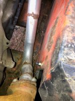
OK
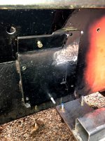
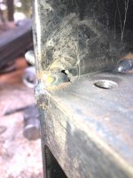
Countersunk the hole and inserted a flat head Allen bolt....Drilled out the threaded hole in the flange plate and through the tub too..

Threads and nut can be seen in one piccy close to the head pipe.....

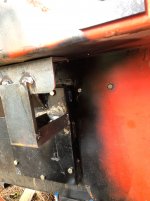
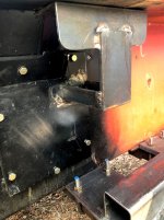
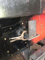
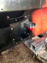
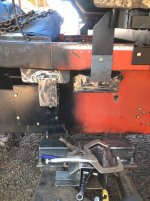
The channel base for the bumper is seen tacked to the cover plate...Then the outer piece of FB is seen sitting on a temporary piece...clamped in place....Tack welded to the channel.....

The angle support that goes under the ledge of the tub is tacked to the FB upright.

Holes drilled through the tub ledge.

Entire assembly off the cat and upside down on the work table....Too windy to weld the stuff up this afternoon....

Tomorrow morning may be quieter wind wise and possibly sneak in a few welds before it gets windy again..

The location on the bump stop bracket will work fine.....Slightly different look due to the different shape of the covers.

Still easy to remove the covers to access the exhaust manifold connections to the head pipes.

Next comes the air bag bracket......After measuring up for the bump stop.....the area just behind the Bump stop is wide open and the air bag bracket will bolt to the tub and to the single bolt on the forward cab mount tube bracket just as it's mate on the RH side has....

Once the upper bag bracket is mounted....the lower perch can be fabricated to match it's mate on the RH side....

Once these parts are done there are some things left to do to the LH axle shaft......

Drill the center hole in the end of the shaft..
Complete the air bag arm hub and then get the parts assembled and mark the shaft for the keyway and the hole for the through bolt....

Inner edge of the hub gets drilled and tapped for the puller attachment bolts.

Also need to weld the shaft to the spindle housing.....

3 of the 4 thrust washers still need machining....Washers are rough cut....Just need a trip to the lathe to get them to size...

Fun stuff for sure......
 

Attachments

  • LH upper bump stop bracket7.jpg
    LH upper bump stop bracket7.jpg
    247.6 KB · Views: 95
  • LH upper bump stop bracket6.jpg
    LH upper bump stop bracket6.jpg
    275.5 KB · Views: 101
  • LH upper bump stop bracket5.jpg
    LH upper bump stop bracket5.jpg
    307.3 KB · Views: 98
  • LH upper bump stop bracket4.jpg
    LH upper bump stop bracket4.jpg
    316.3 KB · Views: 90
  • LH upper bump stop bracket3.jpg
    LH upper bump stop bracket3.jpg
    296 KB · Views: 103
  • LH upper bump stop bracket2.jpg
    LH upper bump stop bracket2.jpg
    399.2 KB · Views: 100
  • LH upper bump stop bracket1.jpg
    LH upper bump stop bracket1.jpg
    407.8 KB · Views: 99
Last edited:
Finished welding the upper bump stop bracket up this morning.
Discovered that the air bag kit was short by 2 of the bag to bracket screws....Ordered up some plus extras.

Weather changed.....hotter than yesterday.....Arrrrrgh...cooler tomorrow and Tuesday.
Will see what shakes.
 
Got after the air bag upper bracket this morning.
Better weather.....
Just plugging away at the pieces.
The upper bag bracket is all welded up and bolted onto the tub now.

The relationship of the air bag bracket and the bump stop bracket are a little different from side to side....The location of actual bump stop is the same....

The difference is due only to the location of the exhaust cover panels (The slight offset of the exhaust manifolds is the cause)

The outer portion of the bracket that bolts to the cab mount assembly is bolted up....just need to tack weld it to the the bag bracket and then remove for the final welding.....

Pretty easy stuff when the other side can be copied fairly close and then built.....

Tomorrow and Wed are gonna be sideways around here...The other half is getting a kidney stone blasted.....
Tomorrow is the Covid test and Wed morning is the procedure....

I may get something done tomorrow afternoon.....not gonna count on anything at this juncture....

I am pleased at how well the pieces are coming together.....

I did scare up a 2-3/4" urethane round bar to make the diffy mounts from....

90 durometer Black urethane....
Once the diffy is back in the chassis and the axle tube ends are snugged into the outer brackets....then we can see whats up and then cut the biscuits...With any luck the lower urethane biscuits can be cut to fit with minimal shimming.

The factory used 16 gauge and 10 gauge shims.....Likely a select fit arrangement to get things spot on......

If I can cut the biscuits to size it will save a lot of fooling around......

The upper biscuits are pretty much along for the ride.....


Fun stuff...

Gonna be lots more fun building the new engine......

Likely the last task will be building the tracks.....

Once the chassis is ready to go.....Then full attention can be directed to the track project.
We have enough grousers, tire guides and backing plates now to do the job.

Looks like the tire guides will be a mix of Gen 1 and Gen 2 style.

Would have been sweet to have been able to scare up two full sets of the Gen 3 style tire guides.

I have a few....but not nearly enough to do even one track.....

The Gen 2 guides are pretty sturdy.

Most of the Gen 1 guides off the 1 track we just got are junk....(Some are repairable....but we have enough good ones....so why screw with the junk)
Track 2 looks like all are Gen 2

I am pretty sure the tracks I got were not from the same machine.....

The one track was a hodge podge of splices, laps and were a mess....

All the rubber went to the trash....The grousers were sorted into RH and LH and the junkers culled out.....

Looking at the stuff we got with the cat ...we did get a lacing grouser.....This will make getting the lacers all bolted on easily.

Track 2 has been spliced with a second lacer set in the middle....Not sure if we have enough hinges to do both tracks with what came on the two.....But I have enough Flexco 550 lacers to do both tracks....(New parts)

Ahh yessss.

It is coming along.

Finally getting enough parts to build the tracks was a big relief for sure....


But we are a fair bit away from tracks as yet.....

Later troops....
 

Attachments

  • LH AIR BAG UPPER BRACKET4.jpg
    LH AIR BAG UPPER BRACKET4.jpg
    385.3 KB · Views: 95
  • LH AIR BAG UPPER BRACKET3.jpg
    LH AIR BAG UPPER BRACKET3.jpg
    304.1 KB · Views: 96
  • LH AIR BAG UPPER BRACKET2.jpg
    LH AIR BAG UPPER BRACKET2.jpg
    339.8 KB · Views: 103
  • LH AIR BAG UPPER BRACKET1.jpg
    LH AIR BAG UPPER BRACKET1.jpg
    346.6 KB · Views: 117
  • Like
Reactions: PJL
Nice work Snowy, I've been following along. Really interested in the steam porting head work when you get to it, cool stuff. No pun intended;)
 
Thank you.

The siamese cylinders required the holes.....I have the factory 400 heads....But aside from the fact that they were junk to begin with...The Vortec heads from the L31 pickup engine will give us better compression ratio (About 9:1 or maybe 9.5:1 if we are lucky.

I bought the stock type dished pistons as they are easy to come by and very reasonably priced.

Still lamenting over the cam I want to use.....
I want a good mid range cam.....But also want a bit of a THUMP at idle.....There are a few choices...

The stock Vortec heads will allow up to about .470" lift without having to machine the valve guides down....and the stock springs are good too at those lower valve lifts.

The Vortecs flow really good in the low .400" range....so why screw around spending $$$$$$$$$$$$$$$$$$$ to get a high lift cam to fit.
The max RPM is gonna be in the 4500 range.....Again, so why spend $$$$$ on special valve springs and other parts.

The stock self guided 1.5:1 rockers (Saved them off the L31) are all in great shape......

Did some snooping around to see what can be had for a good radiator to cool this critter.

Griffin has one that will fit in the 2100 tub (24" wide x 19" tall with 2 rows of 1-1/4" tubes) They rate it at 600 to 700 hp cooling capacity.....

I have the 21" clutch fan that came on the L31 engine (1998 5.7 pickup) and I have a suitable GM fan shroud that is split top/bottom....and with a bit of Franken mods it will fit in the tub....

I thought about electrics to save on room.....but the electric fans will not move as much air that the big belt driven windmill will....Plus the electrics hog more off the battery and alternator.....

The Steam hole project will be into the winter some time before I get to it.....

6 holes in each head...3 that are square to the deck.....and 3 that are on a 30 degree angle so they hit the water passage in the head

Gonna set the heads up in the mill to do the steam holes........

Going to have to make a couple brackets to hold the heads at the proper angles and allow bolting them to the mill table...

Just more fooling around.....
comp extreme energy 4x4 cams have a ton of torque and a good lope many versions to choose from
 
I have spoken with the folks at Comp cams.......They were pretty skimpy on a cam that can work with the stock Vortec L31 heads.
IF....and this is a big IF I decide to machine the valve guide height down....plus cut the spring pockets to accept performance springs...

Then we have a huge selection of cams to look at

One little caveat.

The Vortec heads with stock springs and stock guide height.....about .450" lift is pushing it to the limit..

There are a few choices...../The old 327/350 horse cam is a .447 lift 222 duration.
I had one of those in a 1979 GMC 2500 4x4 with a 400 small block

Had a nice lope at idle and pulled pretty good.

Not the best grind....
Just can't bring myself to want to toss big $$$ into a set up for an engine that is going to run a max of 4500 RPM

The stock L31 pickup engine is redline at around 5000.....

All the trick springs and machine work to go 6500 or more......Not this time.

4500RPM will yield about 15 mph......PLENTY

6000 RPM would yield 20 mph

I don't think 20 mph with the big azz tracks on the 2100 would be advisable....
Even at 43" wide and about 1000lbs each on the tracks....a lot of weight thrashing about.....

The driveshaft also needs to be thought about.

Spinning that shaft at that speed is a tad scary too.

Summit cams has a K1102 and a K1103 CAM
The K1102 is right in the sweet spot on the lift......444 on the EXH AND .421 on the int.
The K1103 cam is .444 and .466

Summit says that it will work on stock vortec heads.

I am going to need to rip the springs off and measure the distance between the spring retainer and the valve seal to see wassssssssup in there for room.

Also the distance between the coils of the spring too....

The stock L32 cam has a lift of .414 and .442
So anything close should be workable.

We shall see as time goes by.....
I really think that the 406 should provide plenty of GIDDYUPGO even with a pretty tame cam.
 
Last edited:
The engine is a 1980 block 400.....The L31 block had the roller cam in it......That block went away...(Sold it)
The Vortec heads use a self guiding rocker arm

I have the complete set of rockers, pivot balls and the nuts...

Yes...the factory stuff would likely be fine for the application.
I thought about going with a roller cam....But need the after market roller lifters.......

Ah whizzzzzz...Just gonna hafta see what shakes out.....

There are several options for sure
 
Back in the groove....
Weather was marvelous today with low 70's this afternoon.

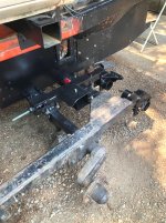
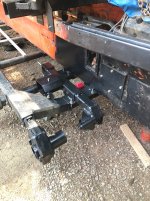
Got the axle shaft welded to the spindle casting......Then stuffed the shaft into the adjuster brackets (Large Red bushings)

Grabbed a long straight edge and got the new axle hub lined up with axle 2 and 3 .... then measured for the thick outer end thrust washer 1-11/16 thick.

Got the washer set all machined and ready to go.

Next comes getting the air bag arm hub situated on the shaft and the key way and through bolt hole located.

Fabricated an elevation fixture to set the LH spindle the same as the RH ...(Same location from the top of the adjuster )

Once the Key way is cut and the through bolt hole is done...then the arm brackets can be welded to the hub and the arm.

Tack these bad boys up and then get the assembly off to weld it up.

The end of the axle needs to be drilled and tapped for the center bolt.
Also need to drill and tap the two holes for the puller to bolt on too.....

So far the entire assembly is very close dimension wise to the RH side....Very small differencesl.....1/16" is all.

Close enough for the crowd I run with......

Made a small running change in the bag arm hub to make the assembly easier to fabricate.

Looks the same...just easier to weld together......

Pics.
Large washer just cut
A couple views of the finished washers
The very inside end washer needs the clearance notch cut to allow the key to clear.
A couple shots with the straight edge getting the front hub lined up with the others.

And away we go.......more fun...
 

Attachments

  • LH LINEUP2.jpg
    LH LINEUP2.jpg
    386.7 KB · Views: 62
  • LH LINEUP1.jpg
    LH LINEUP1.jpg
    457.8 KB · Views: 60
  • LH THRUST WASHERS4.jpg
    LH THRUST WASHERS4.jpg
    381.4 KB · Views: 64
  • LH THRUST WASHERS2.jpg
    LH THRUST WASHERS2.jpg
    333.5 KB · Views: 63
  • LH THRUST WASHERS1.jpg
    LH THRUST WASHERS1.jpg
    419.2 KB · Views: 63
To be honest,I don't read the vast majority of your thread which is filled with unnecessary info such as your water heater went out, the weather in your area, a tool you're using broke, your roof has a leak, etc. ,etc., etc.,. Your project is the first one I've ever criticized for the length of it and God knows life interrupts our projects, but 52 pages and this is where you're at with it? Think of all the progress you could have if spent on the project instead of posting ,like I said TMI !! Now I fully expect to get hammered for this rant but I believe time spent posting 52 pages worth of "details" could have been better spent moving this project forward.....just calling it as I see it.....Bob
 
Build your own cat having the amount of work required as this one has and then call me up and tell me how easy it was.

Folks here like to see the human side of things too.....
This is a family thing ya know..

We all have lives and are not robots with an endless checkbook to toss at a project.....

Rant Off
 
Thanks VB

Not sure how "WELL" we are living...????? :lmao:
The cat project goes back to when I was 16 YO and fell in love with one that was here on the property owned by a contractor building a heavy power line for the local power company.

Nobody in their right mind would try this at home....HENCE the statement by many....Snow cats are a disease with no cure....:thumbup:
 
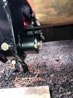
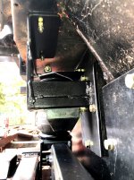
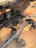
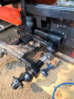
The LH side is getting closer.

Assembled the axle into the adjusters......Got the air bag arm set into the assembly and getting ready to tack weld up the arm to the hub.

Maybe BOB will come over and help me.... :lmao:

Axle shaft is pretty well done...
Key way cut, end of shaft drilled and tapped....Through bolt hole drilled
 
To be honest,I don't read the vast majority of your thread which is filled with unnecessary info such as your water heater went out, the weather in your area, a tool you're using broke, your roof has a leak, etc. ,etc., etc.,. Your project is the first one I've ever criticized for the length of it and God knows life interrupts our projects, but 52 pages and this is where you're at with it? Think of all the progress you could have if spent on the project instead of posting ,like I said TMI !! Now I fully expect to get hammered for this rant but I believe time spent posting 52 pages worth of "details" could have been better spent moving this project forward.....just calling it as I see it.....Bob
starting a sentence with "to be honest" makes one think that normally your not........based on your statement it sounds like you might be bending the truth a bit and in fact you have read most of this thread :LOL:
 
I have been on the Diesel Pickup boards since 2001 and am currently one of the mods at "The Diesel Page".....We see all kinds go through...

I am not offended by this type of post....but do find that it raises a big question ?????????????? WHY do people hide behind their computer and make caustic comments about the work and efforts of others......??????

I scanned this other persons list of posts on this venue, VERY limited input.

Does not appear that they have, or have had a cat.......

Few people realize just what sort of work is involved to even do a basic renovation on a cat using stock parts......let alone whats involved when you get into the depths of trying to design "new parts" and then procuring materials to manufacture said parts, or to modify an existing item to work and maybe do what is needed.

Our troopers here that own these ancient cats (Scrap iron) :lmao: know all too well about the "Roll your own projects"

To make a statement/statements as has been posted about the number of pages as compared to how far along this project is really baffles me.

I spend probably 10 x more physical time researching, figuring (Imagineering) and doodling on paper with my tape measure, digital calipers and such in hand compared to the time out at the cat welding, machining and assembling.

That S10 cab did not jump onto the cat chassis, the new front axle assembly did not come in a box left on the the stoop by THE LITTLE BROWN TRUCK ......

My hat is off to anyone that is willing to step up to the plate and take on even the most basic of rebuilds on one of these old piles of rusty gold.

If not for having the Mill and the lathe in the shop.....I would not have started this project.

Hiring out custom build to suit parts would be so costly.....one could go buy a good used "turn key" machine.

As all of you folks here know ....these cats are a labor of love.......

Some days I may only sit and make sketches to get an idea worked out.....and or possibly make one little part.....But it is satisfying when it comes together.....

I have seen some folks here drag home the most gawd awful looking stuff and turn it into a thing of beauty......This puts a smile on my face...EVERY TIME..... I see the blood sweat and tears that went into these projects.....and appreciate the long hours and the hard labor that went into it..

To the person who can hide behind their computer and write caustic abbreviations on a post and make critical comment of the hard work of others.

I have an abbreviation for Y'all.......Not very lady like...so I will refrain from posting it......Let the imagination fill in the blanks....

Thank you troops for the help, the "Likes" and the comments.....

Yeah....Maybe my posts can get a tad on the WTMI side....But someone out there may well find a useful tid bit that will help them.

This forum is like a family, we all share a common interest...( Likely many) and have lives to live off these pages.....Some of us are retired, others have a day job...... I see many with children.......

The amount of effort it takes these days to just survive in this age of a pandemic and other crap going on sure takes it's toll......

Rant off
 
  • Like
Reactions: PJL
I just reread Bobs post carefully

Instead of wasting my time posting the details of how this project managed to get from Scrap iron to a finished cat.....
Seems I should have just posted a BEFORE picture...and then an AFTER PICTURE.....

Just leave out all the details ......WTMI

Nobody cares about that stuff....


OMG
If that were true.....then there would be no reason to have these wonderful forums to share with others would there ????

That sort of attitude brings to mind a person with a very sorry life indeed....

Whatcha all think ????
 
Top