• Please be sure to read the rules and adhere to them. Some banned members have complained that they are not spammers. But they spammed us. Some even tried to redirect our members to other forums. Duh. Be smart. Read the rules and adhere to them and we will all get along just fine. Cheers. :beer: Link to the rules: https://www.forumsforums.com/threads/forum-rules-info.2974/

Astro van cat conversion

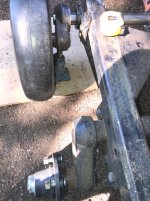
Gathered materials for the inner adjuster assembly yesterday....
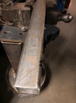
I was able to get the proper size/type of square tube to fabricate the slider parts,

I have to admit....I am still undecided on the choice between the air bag and the Timbren biscuit.....

The Timbren is less vulnerable to damage.....but there is ZERO adjustment.....This worries me..
The 2500 lb air bags can be aired up until the front axle just starts to lift the cat when it is sitting static......

After doing a lot of measuring yesterday ...there is plenty of room in the area to get the 6" diameter bags fit in......
I have worried about this idea based on the bag getting damaged......but possibly a shield around the bag on the side facing the edge of the track will be a plan.
Maybe I am over thinking this a bit ???

One things for sure....the front axle on these cats gets the hell beat out of them.....
Every axle I looked at as a possible replacement was beat to rat crap.....the torsion ends were all worn out and the plastic half bushings in the casting at the tube ends were wasted.

And these are not rebuildable ......
I want to be able to quickly, easily and cheaply refurbish the front axle on the beast....

Ah yessss......and so it goes.
 
More work on the new axles today.
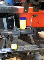
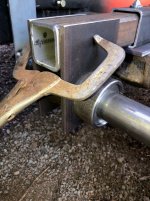
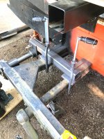
Got the major parts cut and fit......
Waiting on the U bolts I ordered to fasten the inner adjusters to the frame and the second axle.
I hope they get here before the good weather goes away for a while...
 

Attachments

  • Refitaxle6.jpg
    Refitaxle6.jpg
    444.3 KB · Views: 71
  • Refitaxle5.jpg
    Refitaxle5.jpg
    371.7 KB · Views: 69
  • Refitaxle4.jpg
    Refitaxle4.jpg
    329.9 KB · Views: 65
  • Refitaxle3.jpg
    Refitaxle3.jpg
    428 KB · Views: 70
  • Refitaxle2.jpg
    Refitaxle2.jpg
    363.9 KB · Views: 71
  • Refitaxle1.jpg
    Refitaxle1.jpg
    378 KB · Views: 72
Great news.
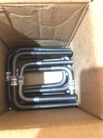
The U BOLTS I ordered for the inside slider/adjuster arrived last night sometime and I found this lovely little box on the deck by the back door........

Todays project is to get all the plates laid out and drilled and then do a temporary trial fit.....IF time permits.

Wet weather coming soon and all the new clean and unpainted materials need to be back inside so they don't rust up.....

Looks like today will be pretty decent working weather.....not nearly as warm as the past few days though.....

Glad to see those parts here....
 

Attachments

  • U Bolts .jpg
    U Bolts .jpg
    254.3 KB · Views: 80
Definitely starting to look like what I had in mind.
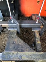
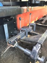
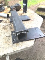
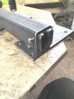
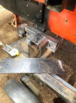
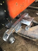
Got the plates all drilled, the parts located and tack welded.....

The wind was howling today....makes mig welding a bitch....tomorrow should be better....

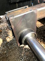
The one piccy shows the slider with a diagonal mark on it. .....Yup...gonna cut that sucker off on a slope to match the original outside slider.

The inner slider is outside the orbit of the track....but not by a lot.

Going to slope the front of the slider and then smooth and round all edges to be sure IF THE TRACK SHOULD MANAGE TO GET OVER THAT FAR.....That it will not catch on anything and mess things up.

Removed the jigs.....Looks good me thinks.

Rain by late tomorrow.....Next will get things welded up more.....Cut the inside slider and weld in an end cover.

Then comes the air bag and brackets.
 

Attachments

  • Refitaxle10.jpg
    Refitaxle10.jpg
    387.3 KB · Views: 65
  • Refitaxle9.jpg
    Refitaxle9.jpg
    511.1 KB · Views: 75
  • Refitaxle8.jpg
    Refitaxle8.jpg
    407.7 KB · Views: 74
  • Refitaxle7.jpg
    Refitaxle7.jpg
    455.7 KB · Views: 75
Decided to make a little Change order......
Pawing through a cabinet looking for some stuff (Unrelated to the cat project) and stumbled across some herky urethane bushings....

Hmmmmm...Urethane bushings would be sweet to support the axle shaft on the cat front axle.

Instead of the HARD UHMW.....
Urethane is used a lot in suspension bushings these days....

So I called around and found an outfit that offers STOCK LENGTH urethane tube 12" long.

I need 3" OD X 2" ID
Perfect....They have it.....About $125 for 4 pieces.

This will make the entire setup much easier.

Will not need the grease seals.....Use silicone lube on the bushings.......The brass thrust washers at the ends of the bushing tubes.

Not really much of a change.....but I think it will be better overall......

No changes to the machined parts that are already done....


And so it goes.....

The sales gal asked me...."WHAT COLOR" ????? Whaaaaaaaaaaaaaaaaaaaaat.????

RED, BLACK, SAFETY ORANGE, GREEN, BLUE, YELLOW....OMG not going to be seen anyway...... :lmao:
 
Got all the goody out of the nice weather today.

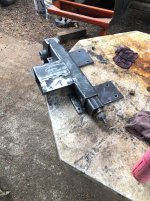
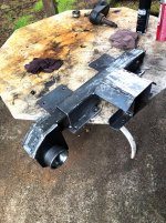
Decided to trim up the inside adjuster assembly before I removed it. (Don't want it rusting in the rainy days that are coming up)
Got the adjuster off, laid out and ....NO WAY TO CUT THE SUCKER.....TORCH...NOOOO WAY.....Thought about tossing it in the mill..
Too much fooling around to do it in the mill.

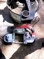
There had been some chatter here about the HAND HELD BAND SAWS....???????????????/
Stopped off at Harbor Freight and dragged home one of their little HAND HELD SAWS.
Damn....that sucker is a sweat heart.
They had them on sale too.......

If you don't have one of these of any brand in your shop.....stop off at the Harbor and grab one.
That bad boy made quick work of the cutting needed.....and they seem pretty well made too.
I got pretty rough with the blade trying to keep things where I wanted.....worked flawless...

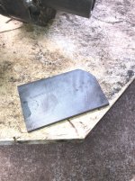
I need to cut a piece of 1/4" X 2" flat bar and finish closing the end of the tube.

When the other side gets done I am going to cut the pieces to match this one before welding it up....

Far easier.....
 

Attachments

  • Refitaxle13.jpg
    Refitaxle13.jpg
    523.7 KB · Views: 71
  • Refitaxle12.jpg
    Refitaxle12.jpg
    436.4 KB · Views: 69
  • Refitaxle11.jpg
    Refitaxle11.jpg
    505.7 KB · Views: 72
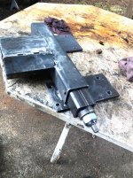
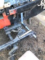
Had some decent time between rain showers....Got after building the ACTUAL adjusting mechanism for the inner track adjuster/axle support.
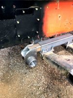
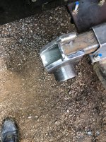
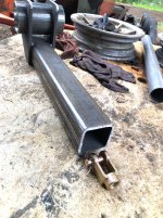
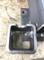
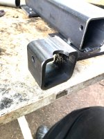
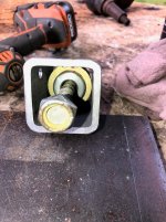
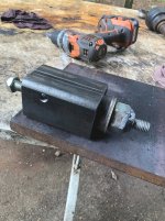
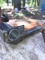
The little box tube with the semi circular cutout is the Adjusting nut housing.
There is a 1" steel plate that welds in the end with the cutout....the cutout is for the grease zerk to fit in.
The adjust nut gets machined from 1-1/2" hex stock and fits into the end plate.
The adjust nut assembly is held in by 2 Shoulder bolts in the outer slider tube.
A piece of 5/8" fine threaded rod gets the clevis on the front end.....Clevis slips onto a piece of flat bar that welds into the slider...to push/pull.

The nut assembly will be greasable to hopefully keep it operational...LONG TERM.
Tomorrow I will get more steel to make the rest of the parts....

The clevis is a standard class 8 truck brake part.....Easy to find...5/8" fine thread.
 

Attachments

  • Inner adjuster5.jpg
    Inner adjuster5.jpg
    451.6 KB · Views: 65
  • Inner adjuster4.jpg
    Inner adjuster4.jpg
    296.5 KB · Views: 69
  • Inner adjuster3.jpg
    Inner adjuster3.jpg
    303.4 KB · Views: 65
  • Inner adjuster2.jpg
    Inner adjuster2.jpg
    381.3 KB · Views: 66
  • Inner adjuster1.jpg
    Inner adjuster1.jpg
    232.9 KB · Views: 67
Yesterday turned into a nasty mess.
A buddy called up and wanted some help on his Thiokol Spryte.....
Needed to drop the tracks and get at all the wheel bearings.....(Yeah....mostly shot..rusty...)

I get to his place and the cat is in the garage..
The first word I hear....HOW DO WE LOOSEN THE TRACK ADJUSTERS.

OMG...The adjusters are the manual type and things are rusted up tight as a bulls azz in fly time.

Did not want to get the torch in there to cut things...and damage the tracks.
I had to run back here to the shop and get my air die grinder and some cut off discs.
We spent a fair bit of time getting the old crap cut off.

Got the tracks dropped loose and my buddy went to work on the bearings.

Now....WHAT TO DO with the adjusters ?????

We are considering adding the grease cylinders to the machine.
Not that much work.....

This scenario brings things to mind that my idea of using a manual adjuster on my inner front axle setup may not be at all a good plan.

To make a pair of cylinders is a snap.
My old ones make great patterns to copy.
Simply and they work great......

I will let my buddy figure out his choice.

For the moment the adjuster plans for my machine are definitely not going towards the manual threaded type device...

The mess we encountered was not worth the effort to just replace it with same.
 
  • Like
Reactions: PJL
Back at it.
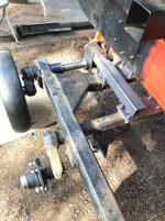
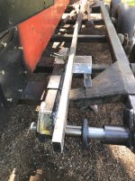
After studying the relationship between the outer orbit of the inner track belt and the NEW INNER ADJUSTER.....It became somewhat troubling .....THERE DOES EXIST a slight possibility that under a worst case scenario the track could dive down and hit the adjuster...

The track sits about 2 inches away from the inner adjuster.....With the rig jacked up and the axles at the lowest point they can travel the track is about 1-1/2" above the top of the adjusters top tube.....

Soooooooooooooo...Decided to add a 4" x 4" x 1/8" box tube 6" long plus some "Wings" to bolt a piece of UHMW to.......This will act like a "Nerf bar" and "IF" the track were to dive down the top track belt will simply glide over the NERF and not hurt anything.

I do not trust the amount of parts and such flying about NOT to do something weird......

The entire assembly is looking pretty good....
I have not ordered the air bag assemblies as yet.

Thinking that tomorrow I will start building the fabrication for the RH side.
I still need to finish removing the old torsion bar and such from the spindle housing for the RH side axle.
I have the U BOLTS and most of the materials.
Still need to get the outer 3" x 3" slider tube.....

I can use the setup jigs and such to get the RH side as far along as the LH is now.....

Still contemplating just how the finished inside adjusters will end up......the grease cylinder seems like the plan.
The idea of a locking device of some sort to keep the axle from wanting to try and walk in and out seems like a plan....????

The 6" wide UHMW can be seen laying on the frame.
A heat gun and form the plastic....then two bolts on each wing...

JUST AN FYI....The orange on the parts is not paint.
Seems to be a reflection from the bright steel catching light off the tub..????? There is not any paint on these parts as yet.
 

Attachments

  • Refitaxle16.jpg
    Refitaxle16.jpg
    406.6 KB · Views: 81
  • Refitaxle15.jpg
    Refitaxle15.jpg
    459.6 KB · Views: 73
  • Refitaxle14.jpg
    Refitaxle14.jpg
    414.4 KB · Views: 79
Last edited:
  • Like
Reactions: PJL
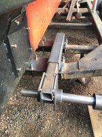
Decided to try a mechanical track adjuster setup on the new inner track adjusters.
The plan sort of came together the other day....decided to sketch it up....Awe hell....lets make it.
Machined up the parts and welded stuff together.
Unit slides into the outer tube ....has a threaded rod that connects to the inner axle support and an adjuster unit.
The adjuster was simple enough.
A sleeve with the threaded portion inside of a tube that slides into the main support tube.

We shall see just how well it works....I fitted the beast up with a greasing device to help keep the threaded rod and the adjust from rusting.
One 3/8 grade 8 bolt secures the adjuster into the unit....If it goes south.....simple to pull the bolt and slide the entire unit out.....
 

Attachments

  • LH ADJUSTER5.jpg
    LH ADJUSTER5.jpg
    505.8 KB · Views: 76
  • LH ADJUSTER4.jpg
    LH ADJUSTER4.jpg
    573.8 KB · Views: 68
  • LH ADJUSTER3.jpg
    LH ADJUSTER3.jpg
    513.8 KB · Views: 75
  • LH ADJUSTER2.jpg
    LH ADJUSTER2.jpg
    354.5 KB · Views: 77
  • LH ADJUSTER1.jpg
    LH ADJUSTER1.jpg
    324.6 KB · Views: 75
  • Like
Reactions: PJL
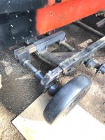
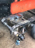
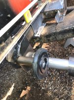
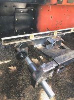
Spent a short time today adding a "Donkey Wheel" out front on the LH assembly to make certain that the track can't interfere in a worst case scenario
A similar setup can be seen on the Pisten Bully in a couple key places near the front road wheel.....


The little wheel stud is welded in.....still need to add a couple gussets....need to wait until the inner bushing tube is located and welded....

The little idler is courteous of a snowmobile I owned back in 1979....These were still on the shelf....
Easy to replace and pretty sturdy.....
Noe they have a job....
 

Attachments

  • LH AXLE DONKEY WHEEL3.jpg
    LH AXLE DONKEY WHEEL3.jpg
    420.7 KB · Views: 78
  • LH AXLE DONKEY WHEEL2.jpg
    LH AXLE DONKEY WHEEL2.jpg
    429 KB · Views: 74
  • LH AXLE DONKEY WHEEL.jpg
    LH AXLE DONKEY WHEEL.jpg
    377.2 KB · Views: 139
Been a bit slow around here...at least as far as the cat goes.
Other stuff got in the way.....

Finally got back at it today.
Cleaned up the shop and got a big bunch of plastic TUBS, TOTES, STORAGE BOXES and gathered up all the parts for the cat......
Bench actually has a top that can be seen now..

Cut the steel pieces for the RH front axle inner adjuster assembly......
Tomorrow if all goes well I will get the holes drilled in the frame mounting plates for the inner adjuster.

Sure nice being able to find all the bits and pieces and have a fairly neat work area.

YES IT WAS A REAL CHITHOLE.....
 
Decided to move to the RH side and get it caught up to where the LH front side is now.
The Spindle/casting cut off has been on the table out in front of the cat for quite a while.

I had chopped it off a used axle last fall...

By the looks of things (Welds) it had been re-welded .....

Tossed that bad boy in the vise and buffed off the rust and grunge......
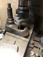
Next it was to the mill to get the old weld chopped off and find the joint between the casting and the torsion bar....

That center bar is HARD....chips come off blue or red.....

Got the break lines showing all the way....to the press and shove out the old bar.....The LH one took 50 tons to get it loose.....this one was pushing my 20 ton to the limit.....but it came out..... :clap:


Off to the mill to get the back end of the casting square with the hub ( It is as cast....)

Then flip the sucker over and into the table vise.

Indicate the square bore (Best I could) stuffed in the boring head and let it rip.
The square bore leaves things with an interrupted cut .....so its a slow slog....Light cuts and slow speed..

The casting is not hard.....but still very good material.
Chewed on this sucker until the bore measured 1.993"
The new shaft is 1.9975" (2" cold rolled steel)

Finished deburring and it's ready to go on the new shaft.....

Gonna heat that bad boy up hotter than hell and damnation and slip it onto the shaft......

Good to go.

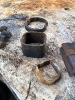
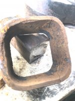
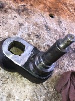
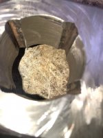
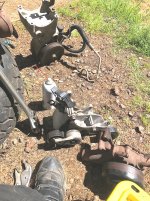
Some pics of the spindle as I cut it apart.
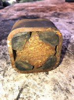
The torsion unit was Fubar'd
The inner nylon guide bushing...JUNK
The axle tube was cracked badly too....
The outer split bushing was still in fair shape.....

The spindle proper is lovely......

One spot on the casting showed a nerf where one of the axle bolts had come loose....no worries....weld it up and dress it off with the grinder...... (LH side near the back of the spindle while in the mill to cut the back square....the nerf is apparent)

Overall the spindles (RH LH) are great parts and will give years of service......
 

Attachments

  • RH SPINDLE1.jpg
    RH SPINDLE1.jpg
    406.1 KB · Views: 67
  • RH SPINDLE2.jpg
    RH SPINDLE2.jpg
    411.7 KB · Views: 70
  • RH SPINDLE3.jpg
    RH SPINDLE3.jpg
    264.2 KB · Views: 71
  • RH SPINDLE6.jpg
    RH SPINDLE6.jpg
    220.3 KB · Views: 69
  • RH SPINDLE10.jpg
    RH SPINDLE10.jpg
    381.3 KB · Views: 70
  • RH SPINDLE8.jpg
    RH SPINDLE8.jpg
    299.7 KB · Views: 72
  • RH SPINDLE9.jpg
    RH SPINDLE9.jpg
    245.6 KB · Views: 75
  • RH SPINDLE11.jpg
    RH SPINDLE11.jpg
    406.1 KB · Views: 68
  • RH SPINDLE12.jpg
    RH SPINDLE12.jpg
    232.2 KB · Views: 79
Last edited:
  • Like
Reactions: PJL
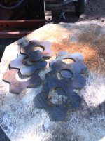
Finally got the notice that the last six "Snowflake" wheel centers were ready to pick up....

Got them suckers home.

These will give us plenty with a few extras on the shelf....
 

Attachments

  • Last snowflakes cut May 11.2021.jpg
    Last snowflakes cut May 11.2021.jpg
    415.4 KB · Views: 67
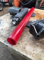
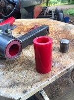
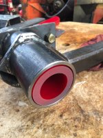
Got a call from Griffith Polymer earlier today.
The custom urethane bushings were ready to be picked up.

3" OD X 2" ID......36" LONG (CUT TO SUIT)
Ordered two 36" pieces....They have a $100 minimum order and 1 piece would make the needed bushings....but two pieces were $166....Will make a spare set.

This is 95A scale urethane.(Same durometer as the common urethane spring bushing that are sold by the 4x4 parts guys in the ENERGY suspension brand)
It cuts really nice in the band saw.

All ready to slip in and go to work.
 

Attachments

  • New REDBUSHINGS3.JPG
    New REDBUSHINGS3.JPG
    400.3 KB · Views: 59
  • New REDBUSHINGS2.jpg
    New REDBUSHINGS2.jpg
    390 KB · Views: 61
  • NEW REDBUSHINGS1.JPG
    NEW REDBUSHINGS1.JPG
    298.2 KB · Views: 62
Not much happening today.
Started working on the RH inner track adjuster....Then the weather went south.
Soft hail balls 1" in diameter and rain....wind.
Crazy weather.
34 F this morning......Cold for late May...
 
With the weather being nasty...Decided to get after the 400 inch Small block and get it ready.

I tapped the 3 oil passages in the front (Cam galleries) for 1/4" pipe plugs.....The little soft plugs literally fell out when I ran rod down the passages....

Tapped holes will be far better..Blue Loctite will keep the plugs in fine.....

Got that job done and then loaded the block up and hauled it off to Machine shop.
A couple cylinders have some rust thats a tad deeper than surface rust.

Want to make sure that the holes will clean up at .030" OS before I trip the trigger on the new pistons.....

While the block is at the shop they can stuff in a set of cam bearings.......

Should know wasssssup in a few days......
 
The word came back today......The one ugly cylinder cleaned up at .020" OS..
The next step is to get the .030" OS slugs coming.....
 
  • Like
Reactions: PJL
Weather good
Back at the Fab work on the RH track adjuster/axle set up.
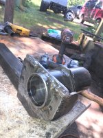
Got the add on plate bored to fit into the original adjuster to allow the new tube to weld in.
The plate bolts in to locate it.....then will weld in after everything is all dialed in.
The LH mate to the assembly for comparison.
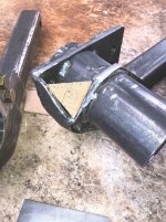
Also going to add a small gusset in the corner...(Cardboard template in the pic)
The add on plate bored and bolted in place....New pivot tube slips in real nice.
The inner plate is shown without the hole bored..

Tomorrows job....rain is back....
 

Attachments

  • RH ADJUSTER FAB5.jpg
    RH ADJUSTER FAB5.jpg
    436.7 KB · Views: 63
  • RH ADJUSTER FAB4 .jpg
    RH ADJUSTER FAB4 .jpg
    405.2 KB · Views: 67
  • RH ADJUSTER FAB3.jpg
    RH ADJUSTER FAB3.jpg
    406.5 KB · Views: 82
  • RH ADJUSTER FAB2.jpg
    RH ADJUSTER FAB2.jpg
    354.5 KB · Views: 66
  • RH ADJUSTER FAB1.jpg
    RH ADJUSTER FAB1.jpg
    309.4 KB · Views: 65
In the shop watching the rain come down and listening to the mill running away.

Certainly not the most fun part of this project for sure....

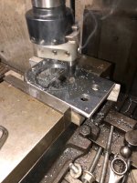
Got the last parts that needed to be bored to allow fabricating the New RH track adjuster completed.

A real Boring job...NO PUN INTENDED.

Stuff looks good.
Sadly the original outer adjuster was not the original parts....or at least not all of it anyway.....But earlier I was able to get both of the outer adjusters machined to at least match each other.
Now the new parts should keep both axles looking at each other....(Straight and level)

Some pics
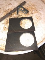
The inner adjuster tube side plates (Still need to have 2 corners trimmed off )
The outer assembly looks good and the new parts fit well......
Next comes jigging it all up and then welding stuff together.

The inner adjuster tube needs the end cut on an angle for clearance (Scribe line can be seen in the piccy)
 

Attachments

  • RH ADJUSTER FAB8.jpg
    RH ADJUSTER FAB8.jpg
    384.5 KB · Views: 59
  • RH ADJUSTER FAB7.jpg
    RH ADJUSTER FAB7.jpg
    206.9 KB · Views: 61
  • RH ADJUSTER FAB6.jpg
    RH ADJUSTER FAB6.jpg
    349.1 KB · Views: 63
Life is good.
Got shipping / tracking on the new pistons, cam bearings and a couple other goodies for the 406.....
Building an engine one nut bolt and screw at a time is fun...yeah right.

I got very little in the way of parts with the 400 block.
Timing cover and the balancer was about it.
Slowly scraping the rest together.
Need standard push rods.
Oil pump and bolt and oil pickup tube
Pump drive shaft.
Got the large oil pan and bolts...
Here is hoping the Vortec heads are good......
4 bolt valve covers on the vortec are good to go
All the front serp brackets and such are all on the Vortec....Fan and such too are there
Need the externally balanced flex plate and crank bolts.
Need front crank snout bolt and washer
Need a fresh large cap HEI distributor...
Exhaust manifolds in the cat on the 305 are new...good there

Indeed a "Frankenmouse"
 
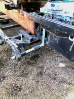
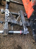
Got more fab work done on the RH axle/track adjuster assembly yesterday....

Got the jigs from the LH side all lined up and clamped in place.....

Stuffed the new pieces in and let them all fall into place....
Looking promising.....
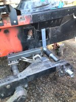
The outer assembly (Original part plus the new pivot tube) all lined up really well

With as much damage as was done to the original axle....I am really surprised that the frame did not sustain any damage.

The main frame on the 2100 is definitely stout.

The outer assembly is pretty well welded up now.

Tomorrow the inner slider tube gets trimmed on an angle and the side plates as well.

Then the inner adjuster can come together......

Some pics.

The bracket bolted to the tub is just a guide jig to keep the assembly aligned during the fabrication process....Same as we did on the LH side.


With the axle and spindle/casting ready to go this thing can come together pretty quick now.

A bit more welding and then the new parts can be cleaned and painted......then the bulk of it can be bolted onto the cat.....Hopefully for the final time.....
 

Attachments

  • RH ADJUSTER FAB12.jpg
    RH ADJUSTER FAB12.jpg
    459.3 KB · Views: 65
  • RH ADJUSTER FAB11.jpg
    RH ADJUSTER FAB11.jpg
    509.5 KB · Views: 62
  • RH ADJUSTER FAB10.jpg
    RH ADJUSTER FAB10.jpg
    561.7 KB · Views: 65
  • RH ADJUSTER FAB9.jpg
    RH ADJUSTER FAB9.jpg
    482 KB · Views: 58
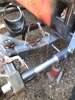
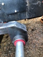
Another leap forward (Small leap)
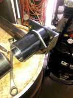
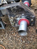
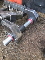
Inner slider tube pretty well assembled (Just need to locate the pivot tube once the air bag arm can be fitted.
Brass thrust washers go in the assembly in 4 places.
After things cooled off I grabbed the polymer bushings and stuffed them into the lash up to have a peek see.

Oh yeah buddy......this is looking good.

Going to be good support on the axle shaft.....

Sitting there the last couple days looking at things got me to thinking......Having the panel off to mount the setup bracket let me look at the side of the oil pan (Hole was cut by the PO to gain access to the starter.....)
I cleaned up the GAWD awful mess and added the frame and cover plate....

The original oil pan sump dropped into a deep pocket in the tub.....The little Chevy pan sump is in the rear......

The 305 pan clears the bottom of the tub by about 3/4"
I bought a gated road race pan for the 406.....and it is 7-1/2" from the rail to the bottom of the sump

I crawled down and took a peek at the pan and the tub...decide to grab a tape measure and get a visual on the actual distance from the pan rail to the floor of the tub. 8-1/4" (The engine sits parallel to the floor of the tub)
Sweeeeeet
Planning to remove the old sump in the tub.......It is about 8" deep (Ford 391)
Just something more to crash into stuff hanging below the tub like it does.....

The one access cover got a revamp last summer to clean the mess up....and it allows a good chance of being able to replace the starter ......
Going to use the mini starter used on the Vortec pickup engine (68 TOOTH FLEX PLATE)

Very small and fits the 400 easily (Angle bolt pattern)

The new battery tray is just aft of the engine above the starter... fastened to the top flange of the tub.....Very close and easy to get power to the starter and also the cab.....

Trying hard to keep this FrankenCat from being a real BASTARD to work on...
 

Attachments

  • RH AXLE FAB16.JPG
    RH AXLE FAB16.JPG
    443.6 KB · Views: 57
  • RH ADJUSTER FAB15.JPG
    RH ADJUSTER FAB15.JPG
    434.3 KB · Views: 58
  • RH ADJUSTER FAB14.JPG
    RH ADJUSTER FAB14.JPG
    513.9 KB · Views: 64
  • RH ADJUSTER FAB13.JPG
    RH ADJUSTER FAB13.JPG
    495.5 KB · Views: 65
The hay season is about here and the Vortec 350 parts engine was in the way to back the big trailer inside to unload hay.....

Dragged that beast out and ripped it apart.
HEADS OFF.
SERP DRIVE ALL OFF
Gained several needed parts......bolts and such
Head bolts are good shape...standard grade 8 washer headed stuff
Crank pulley/balancer bolt and washer...
Heads look good....will snoop at them tomorrow for any issues.......
All the serp drive parts are sweet.....all the factory bolts nuts and such....1998 version is a lovely addition to the project.....
Valve covers are good shape (4 center bolt type)

Gonna try to sell off the short block and extra stuff thats not needed.
 

Attachments

  • VORTEC PARTS2.jpg
    VORTEC PARTS2.jpg
    632.2 KB · Views: 66
  • VORTEC PARTS1.jpg
    VORTEC PARTS1.jpg
    451.4 KB · Views: 65
  • Vortec parts3.jpg
    Vortec parts3.jpg
    509.2 KB · Views: 61
  • Like
Reactions: PJL
Houston.....do you copy....C'mon.

We came home to a Widdle box on the steps.
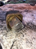
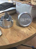
WE HAVE PISTONS FOR THE 406 CAT ENGINE.
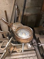
The look great.....Checked all 8 of them for any travel damage....GOOD TO GO.
So now we can bore the block and get the rods and pistons intimate......

Busy today so no cat work happened....But I managed a few minutes to dream up a little jig to drill the steam holes in the Vortec heads.

For anyone not familiar with the Small block 400 Chevy....These beasts have siamese cylinder bores (No coolant flows between)
The block has 6 "steam" holes ...2 between each of the inner bores so coolant can purge through and not make steam pockets.

The original heads have these.....The vortec heads will bolt right on.....just have to use the 400 gasket as a guide and drill the holes in the heads. (3/16" max diameter)

I am going to make an aluminum fixture (1" X 2" bar) and machine it so the two center bolts will allow the fixture to bolt to the block and then drill through the holes and through the head deck.....

One hole must be on an angle of about 15 degrees or so towards the exhaust port...and the other is straight through.

Using a fixture will allow doing this job with a hand drill.....

Yessssssssssssssssssss......I'm getting excited.
 
Hmmmmmm

Thought I posted a piccy of the shiny new pistons

There we go......
Gonna look better when they are peeking out of the holes in the block :thumbup:
 

Attachments

  • New pistons.jpg
    New pistons.jpg
    256.6 KB · Views: 61
Got a fella wanting that Vortec short block SOON
So decided to clean the heads up and see if they were good.

Yanked out the valves/springs a pair at a time and have a peek see.

Everything looks great...No cracks between the seats, not anything presenting elsewhere either...

Valve stems are very nice fit in the guides too.....

The plan is to take the heads back apart and clean things well...then do a light lap job between the valves and seats to freshen them.

They simply do not need anything more than this.
Fresh set of guide seals and it's off to the rodeo.

I feel very pleased that these Vortec heads were not junk....
The urban legends say that Vortec heads....although great power makers tends to be junk as they age.

So we are good to go there.
they are good heads they just dont usually survive an overheat
 
Top