-
Please be sure to read the rules and adhere to them. Some banned members have complained that they are not spammers. But they spammed us. Some even tried to redirect our members to other forums. Duh. Be smart. Read the rules and adhere to them and we will all get along just fine. Cheers. :beer: Link to the rules: https://www.forumsforums.com/threads/forum-rules-info.2974/
You are using an out of date browser. It may not display this or other websites correctly.
You should upgrade or use an alternative browser.
You should upgrade or use an alternative browser.
542 Cab Forward Restoration
- Thread starter GMoose
- Start date
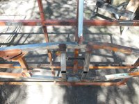
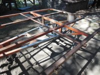
I then added four 1-1/2" wide x 1/4" thick plates to three sides (not the bottom) of each main rail (1-3/4" x 0.120 wall square tube) in the area where the rails had failed. I extended the new plates clear up to the next cross member. Hopefully this will prevent future frame failure, or it may just move the failure points to new locations, use will tell.
Here are the fitted plates piled on top of the frame.

Here they are welded on. First I welded both sides on then ground any of the crown off that extended up over the top surface. I then welded the top plate on. Also added an angle to the ends of the plates to match the angles the factory put on their reinforcement plates elsewhere on the frame. I used full length welds instead of skip welding because I wanted the added strength. The one drawback to this is if a longitudinal weld crack starts it can propagate down the entire length of the weld. With skip welds the crack will stop at the non-welded region and hopefully not continue on down the rail. Hopefully my full length welds was not a mistake.

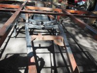
I then built an angle iron cross brace to weld in by the forward most pivot bushing. This bushing gets most of the load when turning so I thought it would be good to give it more strength. The frame I bought last spring has a similar support, that appears factory made.

Here it is placed where it will go. I put it behind the bushing so it will not interfere with the pivot pin, once installed. I will weld it in after I get the bushings welded in and reinforced.

Here are the fitted plates piled on top of the frame.

Here they are welded on. First I welded both sides on then ground any of the crown off that extended up over the top surface. I then welded the top plate on. Also added an angle to the ends of the plates to match the angles the factory put on their reinforcement plates elsewhere on the frame. I used full length welds instead of skip welding because I wanted the added strength. The one drawback to this is if a longitudinal weld crack starts it can propagate down the entire length of the weld. With skip welds the crack will stop at the non-welded region and hopefully not continue on down the rail. Hopefully my full length welds was not a mistake.

I then built an angle iron cross brace to weld in by the forward most pivot bushing. This bushing gets most of the load when turning so I thought it would be good to give it more strength. The frame I bought last spring has a similar support, that appears factory made.

Here it is placed where it will go. I put it behind the bushing so it will not interfere with the pivot pin, once installed. I will weld it in after I get the bushings welded in and reinforced.

It is time to give an update on the 542CF restoration, sorry for the loooonnnggg delay since the last post. First I lost both my helpers, son 1 got a girlfriend and son 2 decided to join the Marines.
Since the last update most of the engine machining has been completed and major parts have been procured (some are very hard to come by for this engine), but I will save those details for later, since I am currently working on the frame.
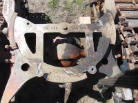
I have also procured the 543 frame from the Spokane Washington area so that I can use the rear trunion plate. Mine is on the front and had been damaged at one time and scabbed back together. I haven't taken this one off the unit yet, but it looks like it will work.
View attachment 117967
I also purchased the 500 series pontoons from the Tucker factory, leftovers from their most recent vintage restore.
"Mine has three right side pontoons",
the left rear was replaced at one time. So with these pontoons I now have the correct pontoons. Looks like one of them will work, will know more later when I get it torn apart. If not, I have spares.
View attachment 117968
thank you Gmoose for sharing, you have done tons and tons of work....
seems like I learn always learn something new on the forums,
thank you Gmoose for pointing out the fact, that there are left and right side pontoons, did not know that, and probably have put together a couple machines with all right side pontoons, if you can, please tell me how to tell the difference between the left and right pontoons...thank you in advance
Well this is all my guessing that there are a left and right pontoon. But on my 1966 unit each pontoon has only one travel stop to engage with the trunnion plate. One of my pontoons has the stop on the wrong end of the pontoon to engage with the trunnion.
1966 pontoons from my 542CF:


Now the 1970 set of pontoons I purchased has stops on both the front and rear inside of the pontoons. Must have been a change they made after 1966.
1970 pontoons, you can see both stops on the far pontoon:
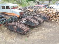
If I am wrong on this please teach me, I am new to the Tuckers, anything I can learn will only help me rebuild this unit correctly.
1966 pontoons from my 542CF:


Now the 1970 set of pontoons I purchased has stops on both the front and rear inside of the pontoons. Must have been a change they made after 1966.
1970 pontoons, you can see both stops on the far pontoon:

If I am wrong on this please teach me, I am new to the Tuckers, anything I can learn will only help me rebuild this unit correctly.
ah, left front with only one stop will swap to right rear and right front to left rear, most pontoons have two stops, sometimes they get removed for any number of reasons and sometimes the factory to save money would only put one stop on
from what I know, which is very limited, there is no left or right side pontoons, only condition that applies, if there is one stop and then it is either a left front to right rear set up, or right front to left rear and later pontoons came with 2 stops, though, very early tuckers had stops and then they went away only to come back somewhere in the mid to late sixties..and if it has 2 stops fit any position, so many variables with tucker and there manufacturing standards...then if the pontoon has only one adjustable nose, your guess is as good as mine, good luck
from what I know, which is very limited, there is no left or right side pontoons, only condition that applies, if there is one stop and then it is either a left front to right rear set up, or right front to left rear and later pontoons came with 2 stops, though, very early tuckers had stops and then they went away only to come back somewhere in the mid to late sixties..and if it has 2 stops fit any position, so many variables with tucker and there manufacturing standards...then if the pontoon has only one adjustable nose, your guess is as good as mine, good luck
Thanks for the clarification on the pontoons! That will help when I start working on them.
fyi, the real issues come from the steel pontoon being a uni-tub construction, with rust being the problem, as no steel pontoon was ever painted inside along with not being completely welded/sealed up, very poor quality construction, thus, they rust badly from the inside out, unless you open them up, you are risking all your work and a long walk out, you absolutely need to open them up and do a full and compete rebuild, there are stresses and forces that are placed upon the pontoon that you just can't image, simply, they are structurally weakened from the RUST.
the best solution is to have fiberglass pontoons, they are a vast improvement over the steelies. even the most destroyed looking fiberglass pontoon are far easier to repair and make right. very much worth buying a fiberglass pontoon tucker just for the pontoons and swap them out.
unless you are lucky enough to have NOS steel pontoons...
Thanks for the advice, I will open them up when I get ready to rebuild them. The steel is in fairly poor shape as it is so most likely they will be needing a lot of it replaced.
A word of caution, There are people who thought it was a good idea to foam the inside of pontoons. Check for this as the foam and flame creates a very bad situation for you.
Acts like cheap cast aluminum when I welded it. Don't think they got any type of heat treatment other than the hot pour.
Need some help from the Tucker experts out there.
Does anyone know what aluminum alloy the fifth wheels are made of, and if any heat treatment was performed on them after casting.
View attachment 118223
call Clyde at the factory, he can answer all your questions
Here they are all welded in. Next will be to ream out the bearings back to size. Welding shrunk them, the amount oversized we guessed on was not enough to allow post-weld clearance, plus they are not as round as before. Adjustable reamer is on order, should be here next week. Once the trunion pin fits in the bearings I will drill and tap both bearings for the grease zerks.

There should be plenty of material on this trunion support and rear frame area now to prevent breakage. Maybe a little excessive, but oh-well. I will just have to make sure the machine is moving prior to steering and it should last, I guess.

There should be plenty of material on this trunion support and rear frame area now to prevent breakage. Maybe a little excessive, but oh-well. I will just have to make sure the machine is moving prior to steering and it should last, I guess.
New seats came this week. Bought the ones for a 55 to 75ish jeep. Look to be fairly close. The one for the drivers side looked more like the 76 and later version, but I decided to go with the earlier version since the cat is a 66. Maybe the drivers seat was changed out at some time. It is obvious that the passenger seat was, it was a kitchen chair.

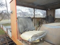
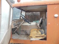


OK, more help from the Tucker experts please. This is way premature but I need some help with the color of the stripes on the cab. I plan to paint the machine the original orange, but if you look at this old brochure you can see that the cab has three "racing" strips up and over the cab. Does anyone have an idea what color these strips might be. Thanks!


they were Red !
but pretty sure yours did not have racing stripes, the machine in the photo, probably was the only one or two, ever to have the go slow stripes,
they are cool and look good, I myself would do the stripes, but wide ones, like from a '69 Camero
but you can always call Clyde, he is the man/expert with all the answers...
Last edited:
they were Red !
but pretty sure yours did not have racing stripes, the machine in the photo, probably was the only one or two, ever to have the go slow stripes,
they are cool and look good, I myself would do the stripes, but wide ones, like from a '69 Camero
but you can always call Clyde, he is the man/expert with all the answers...
Well thanks. I also believe mine did not have them, nor the blade, but I might just add the stripes. Not sure on the width, I kind of like the ones in the pictures. Guess I have a lot of time to decide. Thanks again!!!
Now for the next Tucker expert question of the day:
The original storage box on the back behind the cab, was it made of aluminum or steel? Mine had one at one time, you can see where it was bolted on. It must have been destroyed then replaced with the shorter, but wider, one in these photos. I can determine the dimensions of the original box from the area on the frame where it was bolted and scale from the pictures, but if anyone knows exactly or has better photos then the ones above that would be great.


The original storage box on the back behind the cab, was it made of aluminum or steel? Mine had one at one time, you can see where it was bolted on. It must have been destroyed then replaced with the shorter, but wider, one in these photos. I can determine the dimensions of the original box from the area on the frame where it was bolted and scale from the pictures, but if anyone knows exactly or has better photos then the ones above that would be great.


no expert here, just a minion,
I have a 542 and the box is aluminum. fyi, not all cab forwards had the tool boxes.
it is too bad Clyde does not participate on the forums, he has all the factory records and would be able to answer these questions with some authority, it would be an asset to the collectors of tuckers
I have a 542 and the box is aluminum. fyi, not all cab forwards had the tool boxes.
it is too bad Clyde does not participate on the forums, he has all the factory records and would be able to answer these questions with some authority, it would be an asset to the collectors of tuckers
no expert here, just a minion,
I have a 542 and the box is aluminum. fyi, not all cab forwards had the tool boxes.
it is too bad Clyde does not participate on the forums, he has all the factory records and would be able to answer these questions with some authority, it would be an asset to the collectors of tuckers
I will make the new one from aluminum then. It is obvious to me that this one had the box, there is an opening in front of the plywood bed but behind the cab. And there are old bolt holes in the frame in this area. Thanks again for the help!
I will make the new one from aluminum then. It is obvious to me that this one had the box, there is an opening in front of the plywood bed but behind the cab. And there are old bolt holes in the frame in this area. Thanks again for the help!
as much as I like to restore to original specs, I would not put the box back on, but rather create a storage area in the coffin and have a hinged door in the floor of the flatbed, the coffin area is just wasted space, unless you take the fuel tanks out of the cab and built a custom tank in the coffin area, thus giving you more room in the cab, that would be the best choice IMHO.
thank you for posting the photos of the restoration.....
olympicorange
Active member
Here they are all welded in. Next will be to ream out the bearings back to size. Welding shrunk them, the amount oversized we guessed on was not enough to allow post-weld clearance, plus they are not as round as before. Adjustable reamer is on order, should be here next week. Once the trunion pin fits in the bearings I will drill and tap both bearings for the grease zerks.
View attachment 118266
There should be plenty of material on this trunion support and rear frame area now to prevent breakage. Maybe a little excessive, but oh-well. I will just have to make sure the machine is moving prior to steering and it should last, I guess.
………..'' over-kill' on upgrades for a wear/stress point is not necessarily a bad idea... usually a good plan,... but that old saying...'''the weakest link in the chain'''...scenario.... looks great ...

The adjustable reamer came this week so I was able to get the trunion bearings back to size and in alignment after welding. Took many cut, a few thousands at a time, long tedious job. Final results were very good. the spiral cut reamer worked very well. I built a tapered bushing to install into the bearing not being cut to align and stabilize the reamer, worked well.

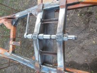


Here is the trunion pin installed (proof that the reamer worked). I am going to make a washer to go on the end where the angle head is attached (left side of this photo). The angle head (I am sure there is a better name for it) is welded to the shaft with a fillet weld. This fillet weld is basically a tapered wedge that gets pushed into the bearing inner diameter when the cat moves backwards. This has got to lock things up from rotating side-to-side, and introduce some forces I really don't want in the bearing. I am going to build a washer which will go over this area and give a flat bearing face which will carry the load between the face of the angle head to the face of the new bearing (basically span the fillet weld). Once I get it built I will show some photos. Hopefully this will do two things: 1) provide a flat thrust face for the loads, and 2) take up some of the slop in the pin, in the axial direction.


