• Please be sure to read the rules and adhere to them. Some banned members have complained that they are not spammers. But they spammed us. Some even tried to redirect our members to other forums. Duh. Be smart. Read the rules and adhere to them and we will all get along just fine. Cheers. :beer: Link to the rules: https://www.forumsforums.com/threads/forum-rules-info.2974/

Question and some advice about a Tucker 1342 "transfer" case

Tacoman

Member
The transfer case (probably not the correct name) was leaking from the front and rear driveshaft seals. I took the drive shafts out and it looks like a pretty easy to replace the seals. I decided to rebuild the brakes and replace the u joints. I still have to ID the u joints and the brake caliper. Can anyone help with that? I can probably match the U joints by measuring them, they look like common Spicers. Does anyone know how to ID the brake caliper and shoes? There were no obvious manufacturing marks on it.

Also would it be advisable to take the t-case out, split it and do a good inspection? My understanding is it a fairly straight forward chain drive. Except for the leaks it seems to be ok. Are there common problems I should be looking for? I am pretty sure replacing the seals will fix the leakage problem. I saw no leakage at the case seam.

Thanks for any help or advice.
John
 
I have a little more information. The unit was built in 1984. The build sheet lists the caliper as Delco 172-584. On RockAuto that crosses to a Cardone 12b2584 but it is not visually similar.

This a single piston caliper. Got everything cleaned up and the only information on it is Delco Moraine and a 18007. Not sure if that is a part number. There were also some random looking casting numbers. Understood from other posts that Tucker used some GM calipers at some point. Does anyone know a way of tracking it down some more information on it?
 
Post a picture of the transfer. I want to see if it is the same as my '69 or the newer much heaver duty unit. Regardless, if you are that point and can easily get to it, yank it and check it. Who knows what life it had before you and how well or if it was serviced. It is the critical part of the whole equation that is made of unobtainium. Unless you have a parts machine already. Best to make sure everything is to spec right now instead of risking it with worn bearings / seals.
 
It will be a day or two for a picture. The t-case is listed as "Gear 1624-1" with a ratio of 1.65 and width of 1.312 on the build sheet.

On pulling it and spliting the case, I was hoping some one would say 'Don't bother, those things are bullet proof'. I suspect the bearings are tapered and need to be shimmed for proper preload and the chain correctly tensioned. I don't have any instructions and I don't want to create problems for myself. Do you know of a source?
 
I guess it depends on what you have. No chains in mine . . .


Trans9.jpg
 
Hey Dan. I may be wrong about the chain but that does not look a lot like t-case. Next time I look at it I will post some pictures.

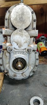
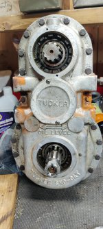
Also I am trying to ID the brake caliper that was on it. The build sheet lists the caliper as Delco 172-584 but I can't find any reference to it on any of the parts suppliers or just doing a general web search. Rockauto, Delco, and the usual suspects. In order from left to right the views are aft side, forward side and from the right side looking in.
Thanks for any help.
John


1000000181.jpg
1000000184.jpg
1000000182.jpg
 
Tacoman,

IIRC, the calipers on your machine are standard GM 1/2 ton pickup units. There is a left side and a right side model for the vehicles, and I don't recall with certainty which one Tucker used (I THINK it's the left side, but please verify that before buying).

My understanding is with your vintage machine Tucker made two transfer cases, both of which are gear driven (no chains). One was the standard-duty model with 1 5/16 wide gears, and a heavier duty unit with 2 1/2" wide gears was available as an option.

Tucker can tell you the proper setup specs for the transfer case, but if there isn't a lot of play, and you don't suspect anything wrong internally, I think I'd leave it alone.

We have replaced seals in the transfer case before by matching up new seals with the part number of the seals we removed. The fallacy in that methodology assumes the existing seals are correct. (Yes, this is the voice of experience.)

We subsequently discovered the correct seal part number is SKF 20098. My recommendation is to start there. It's not uncommon for the seals to wear a groove in the yokes and a "speedi-sleeve" may be required. That part number is SKF 99200.

Note: I'm quite sure these part numbers are correct, but please verify fitment for your application.
 
I will take another look at it this evening. I don't know how I got to thinking it was a chain drive. The existing seal crosses over to a the SKF 20098. Not much of a groove on the yoke but it is leaking from that area. I think I will get the repair sleeves as a belt-and-suspender fix. The seals actually looked OK but it was leaking so there could be something else going on. It might be something as simple of leaking through the spline joint. I plan to seal that also.

Thanks for the help.
 
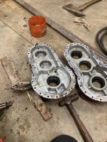
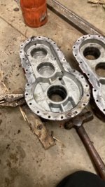
I am back to working on the t-case. I pulled the t-case from the machine, pulled the seals but I have not split the case. Pictures posted. It looks a lot like the t-case that DaveNet posted. Pictures are attached. Couple of questions:
I was going to use the same Locktite 518 gasket forming material to reseal the case. Is there something better?

I have found several possible leak paths:
  • Each of the three drive splines at the yoke. The input will need some kind of a sealed end plug. I may just cut a circular plate and seal that in with 518 .
  • The output shafts already have a thick washer under the bolt and I plan on using the 518 to reseal those.
  • I will use repair sleeves on the shafts under the case seals. Also seal the sleeves to the shafts.
  • The 8 mounting fasteners could potentially leak. There was some silicone or something in there that had gone bad and there was some minor leakage. I was thinking of using Permatex thread sealant. Anyone know of anything better?
  • Am I missing anything?

Any advice on the job, splitting and resealing the case would be appreciated.
Any tricks or things to watch out for?
I will contact Tucker and see if they provide any additional information.

Thanks
John
 

Attachments

  • IMG_20230705_105858.jpg
    IMG_20230705_105858.jpg
    3.5 MB · Views: 54
  • IMG_20230705_105932.jpg
    IMG_20230705_105932.jpg
    2.7 MB · Views: 52
I did the exact same case 2 times last winter once to inspect and the second time to change out a couple gears that were marked very bad thet I noticed on the first inspection) I used the loctite 518 once and high temp rtv once on the case halfs both worked well I had no leaks either time. I used the rtv on the 8 mounting bolt threads both times with no leaks. On my spline input shafts I cleaned both the shafts and yokes very well and coated the inside of the yoke with RTV silicone pushed it on the shaft and tightened the nut with washer with no leaks. One thing to make sure of is make sure the vent plug on top of the case is there, when i bought mine there were screws holding in the seals on the inputs I found that strange. when i first drove it it pshed oil out the seals I decided to dissemble it and found out why. The previous owner put in a pipe plug with no vent when the case warmed up it would pressurize the oil and push it out whever it could. in its previous life it must have built up enough pressure to blow out the seal or seals and it was run dry hence the scalled up gears. I installed a hose barb and short rubber hose vent and now all is well not a drop of leakage. I like the 518 for rigid applications ( case halfs etc) but the rtv for the splines as the clearance is larger and I fing the RTV does a better job when there is a larger gap it is also more flexable than the 518. Here are some picts of my case opened up. If you look closely at the gear you can see where it was run dry
 

Attachments

  • 66812728930__AFF59722-E67E-4770-8255-F6961E0C059D.jpg
    66812728930__AFF59722-E67E-4770-8255-F6961E0C059D.jpg
    94.7 KB · Views: 66
  • IMG_2627.JPG
    IMG_2627.JPG
    94.7 KB · Views: 62
  • IMG_2628.JPG
    IMG_2628.JPG
    92.7 KB · Views: 58
Last edited:
Thanks for the advice. Couple of questions:
What did you do for an input shaft seal? On mine the yoke is intended to slide back and forth on the splined shaft. There is no other slide on the input drive shaft, it is fixed length. This was a major leak path.
You said that you replaced some bad gears. Mine are ok but for future reference where did you find them? I understood they were pretty scarce.
Lastly how did you set the preload between the bearings? There is a youtube video which shows an assembly set with a couple of thou of freeplay, just the opposite of preload. I would have guessed it would either be no freeplay or a couple of thou of preload. Right now mine is set with no measurable freeplay. There is a bearing which is a little questionable and I might change that out. If I do, I would have to go back and set the freeplay/preload.

Thanks again for the input
John
 
Last edited:
I set up my bearings the same as the u tube video with the end play as in the video. My guess to that is tucker assumed there will be more expansion in the gear shaft from the gears meshing than the aluminum casing exposed to the outside air and this difference will tighten the clearance to 0 or a slight preload. It has worked so far perfect my oil is staying nice and clean. My top input shaft is the same as yours but my yoke does not have a hole in it down in the center of the splines ( if you can understand what I mean by that) like a regular one to let the grease out when you grease it. I installed a new outer seal and the yoke slides on the shaft and seals on the outside as this is the only slip yoke to allow for movement. Mine does not leak and the yoke and shaft have a little slop but very little. Is the outer surface on your yoke in good shape to not tear up the seal. You can buy a speedy sleeve for it if it is not. As far as the gears I got lucky and found a used set on the net that were in good shape
 
Supply chain issues hit home. Has anyone priced bearings lately? I was going to replace all six bearing in the t-case. These are a 344a cone and a 332 outer race. That combination will cost about $350 for all six using SKF. Timken was running well over $500. They are pretty hard to find also. If anyone knows of a better supplier or a less costly substitute, let me know.
 
Hey, the bearings will come in next couple of days. I tried to remove the retainer ring for the forward bearing races. I have been soaking it pbBlaster and/or Weasel Pee for about a week. I built a spanner to grab the notches on the retainer ring. I have put quite a bit of torque on the ring but it didn't budge. The spanner I built is not all that great. Is there a trick or a better tool to make things easier? I am a little recluctant to heat the aluminum case but that might be my next move.
 
A terrible thought struck me. Could the retainer rings possibly be left hand threads? It reminded me of an incident with a 1960's International truck. Passanger side wheels have left had threaded nuts. It took me a while to figure that out.
 
There are small allen headed locking set screws if you look at the retaining ring you will see them. They screw into the ring itself to spread it out You screw these in to lock the adjusting ring in place. You nned to loosen or remove these then the retainer ring will screw out easily They are not left hand threaded
 
The lock screws have been removed. The ring is still a lot tighter than expected. I'm making a tool to twist the ring. It has been there long time. Glad to hear it is not a left hand thread.
John
 
Clean the threads real good with brake clean and a small tooth brush and compressed air as they will fill up with debris from the gear wear etc. The threads are very fine work the lock ring back and forth you don’t want to screw the threads up and them being in aluminum they are very soft. My outer races were stuck pretty hard in the casing itself when I first started I couldn’t get the clearance to tighten up. After I removed them and cleaned everything they moved to tighten the clearance as they should
 
Ok, I welded up a tool to engage the wrenching elements on the lock ring. I can get a good solid 80 ft-lbs on it and it does not budge. Does anyone have any experience removing these darn things. I don't want to damage the case so I am not ready to use an air impact wrench just yet. I have applied a little heat and that was no help. I am thinking of bringing the whole assy up to 250-350 degrees in the oven and hoping the different expansion coeffs (steel vs aluminum) will loosen things up. Aluminum has a expansion coeff about twice that of steel. So that would be working in my favor. By my calculations that would only be about .002in differential diametrical expansion at 370degF. But, that might be enough. In the mean time, I will keep giving it thought.

Any other ideas would be greatly appreciated.
John
 
Where the small set screw was screwed into the locking ring when it is removed should leave a gap if my memory serves me correctly. Can you use the dogs that are on the locking ring to tighten/ listen it and squeeze it slightly smaller. Or using a brass punch it you tap on the dogs on the trailing side of the set screw this should actually collapse the locking ring slightly and allow it to start to move. Mine were tight at first and I had to use a punch to get them to break free before I used my homemade spanner wrench to engage the dogs on the locking ring to turn it. I think what was happening is when I tried to initially turn it with my homemade wrench it was expanding the locking ring because it wasn’t made perfectly to engage all the dogs at the same time and wouldn’t let it move. Maybe as you said the different expansion rates will help and maybe even a few heat cycles expanding and contracting will help it break free. Don’t give up and don’t rush it you are playing with a very hard to find piece
 
I have tried to tap it loose at a random cog with no luck. I will try again at the lug with the set screw. I was just going to heat it and try it hot. I will try cycling it hot/cold a couple of times. To see if that helps. Were you able to get the bearing race out prior to removing the locking ring? I am afraid the locking ring may be jammed against the bearing race. My last ditch effort may involve grinding a ledge on the bearing race to tap against. I am going go as slow as I can but it is against my nature. I am constantly fighting the temptation to use a bigger hammer or an impact wrench.
 
My races were stuck pretty good and I couldn’t adjust the end play on the bearings/ shaft that was the main reason I needed to remove the retainer. I got mine out before the bearing race. The heat may do it for you. There is also a product out there to freeze ( for lack of better tems) it shoots out of an aresol like paint can You may be able to heat the unit then hit the retainer with the aresol can stuff to shrink the retainer. It may be enough to break the 2 pieces to allow it to start to move for you. If you are changing your bearings you could cut 2 or 3 small rigges in the outer race with a small zip cut on a air grinder to allow a punch to be able to grab it and drive it inward a little bit to relieve any pressure on the ring. Are all the retainers stuck or only one if it is all of them the PO may have used loctite on them. At around 325f the loctite will let go. Heat the unit and try when it is hot. My guess is they are loctite in there
 
Heat was the key. The casting went into a 300degF BBQ and came out when it was a little over 200degF. Let it cool and back in the BBQ until it got to 200 again. Then spun the retainers with a punch and hammer. One was pretty stubborn but it did come out. Scarred it up with the punch but it is still usable.
When the casting is hot the races almost fall out, when it is cold they are pretty tight.. Everything is clean and ready to assemble.
It was the bronze (or brass) treads on the retainer against the aluminum casting that locked it in. Cutting the race out first probably would not have done much good. It will be reassembled with a lot of anti-seize.

I gotta set the project aside for a little while.

Thanks for the help.
John
 
I hate to bother the group again. I got everthing back together and installed the tcase without the front and rear driveshafts, just to tranny to tcase shaft. Mainly to see if it was leaking oil. I was surprised how much noise it made when it was turning. During normal operation it may not be noticeable with all the additional noise from the differentials and the tracks turning. I was happy with the build, it was silky smooth to turn by hand and the freeplay on the new bearings was set to .002 as recommended. The gears had no wear or pitting on the contact faces. Question: Is it normal for these cases to be somewhat noisy?


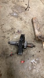
One thing that bothered me when installing the gear set was if they were matched to run in a certain orientation. The center and lower gears are symmetric and can be installed with either end shaft facing forward. I did not see any obvious markings indicating the correct orientation. At the time I convinced myself they were symmetric and didn't matter. I hope it does not have to come out again. It is a PITA. Can anyone shed some light on the situation? I hope this is clear, if it isn't please send me a PM. I can include some sketches or something.
 
I had a brain freeze when writing the prior message. The only gear/shaft where the orientation is questionable is the center gear. The orientation of the upper and lower gears is obvious. The same question applies but only to the center gear.
 
Top