• Please be sure to read the rules and adhere to them. Some banned members have complained that they are not spammers. But they spammed us. Some even tried to redirect our members to other forums. Duh. Be smart. Read the rules and adhere to them and we will all get along just fine. Cheers. :beer: Link to the rules: https://www.forumsforums.com/threads/forum-rules-info.2974/

Kristi tracks

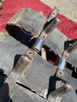
The Flexco lacers are pretty sturdy
My Thiokol 2100 had the 550 Flexco lacers on it....These are shown in the original parts book.

Should be perfect on the little cat


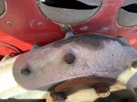
Nice looking machine....Some TLC and it will be great....
 
Stygian: I am sorry, but not sure of your question about the wheel guides and sprockets. Perhaps post some images.

The stainless steel piece on the guides is where the sprocket makes contact on the Kristi. The rest of the design keeps all the wheels aligned without abrading the rubber too much. Yes, it creates some weaknesses and breakage seems to occur at or near the welds. Other vintage machines were configured somewhat differently.
 
The "step/bends" in the grousers is to allow for the thickness of the track belts and to have the surface of the half-round pieces all flush with each other as they travel over the drive sprocket. If you have the "wide'" sprockets it will make more sense. The wide sprockets give MUCH more support to the grousers and prevents the grousers from bending and cracking as the sprocket grabs and pulls each one under load.
 
This drawing shows, I hope what I'm proposing. The top drawing is of the existing "factory" configuration. I recognize the reason for the bends in the wheel guides as noted above. However, I feel that the bottom design would be better and eliminate the weak points in the wheel guides. I do have the narrow sprocket design, by the way.

On my proposed design, I am envisioning a single flat steel bar for the wheel guide, instead of the factory bent configuration. In order to level the stainless sprocket guide with the portion of the wheel guide that is on either side of the stainless, I am adding a small block of steel. This may require making the peaked portions of the wheel guide about .5" taller to keep the same coverage over the wheels and prevent de-tracking. On the grouser/belt side, blocking would need to be added right under the stainless to level that part with the belting so that the grousers have even contact all across the guide.

The only negatives I can see with this design are the added weight, which I think would be negligible. The other is the possibility of the added ~1/4 inch that the belting would "stick out" as a result of not being tucked up in the bent area. This could potentially cause rubbing on the fiberglass. As I said before, I did cut 1/4" off of my floatation belt width. I'm also looking as ways to limit the downward travel as I see where the linkage has contacted and damaged the side of the fiberglass. I've attached a couple of pictures showing that also.

The last thing I'm wondering about is this...see in the picture where the stainless has been flattened. Not sure how that happened, but several of my existing guides look like that. Does it matter?
IMG_6647.jpg
 

Attachments

  • IMG_6640.JPG
    IMG_6640.JPG
    2.8 MB · Views: 60
  • IMG_6642.JPG
    IMG_6642.JPG
    3 MB · Views: 62
  • IMG_6643.JPG
    IMG_6643.JPG
    3 MB · Views: 64
Your idea of using 1/4 inch spacers will probably "work". But I am confident the original designers would have thought of that and probably tried it. It was significantly more work to form the bends and assemble the grousers as they did. They must have determined it was a superior arrangement.
As for the track arms contacting the body, every KT3 I've seen has those marks. I am creating small "notches" with fiberglass to allow for that movement on mine. If any sort of repaint is in your future I recommend you do the same.
 
Top