• Please be sure to read the rules and adhere to them. Some banned members have complained that they are not spammers. But they spammed us. Some even tried to redirect our members to other forums. Duh. Be smart. Read the rules and adhere to them and we will all get along just fine. Cheers. :beer: Link to the rules: https://www.forumsforums.com/threads/forum-rules-info.2974/

Tucker Hydraulic System Help

Track Addict

Bronze Member
GOLD Site Supporter
Need to change all the hydraulic hoses on the pumps, steering, tiller etc. They are getting ready to blow.

Below is a diagram of how my system is setup. I believe it is a vickers pump, ? steering mechanism and a garret tank with filter.

Need some help understanding which way this system flows and understanding why there is a suction line from the tank to the steering?

The rear hydraulics will be getting bypassed.
 

Attachments

  • IMG_0687[1].jpg
    IMG_0687[1].jpg
    31 KB · Views: 402
Sure as hell no expert, but a couple of questions / thoughts with relation to bus systems I know: (sorry no true anwsers since I haven't done mine yet . . .)

I'm guessing some of the lines in your diagram are actually by-pass lines (low pressure) back to the tank. The tank shouldn't be pressurized at all. The "Suction" line from the steering to tank and the "Pressure" line from the Tank to the Pump are probably both by-passes to keep from blowing out the pump seals and steering seals when in a tight turn (or when the snow drag pistons reached full extension).
 
it's not suction there are 2 returns on that system one return is the pressure relief off the pump the other one will be an excess return off the orbital valve .
 
So the line from the steering back to the tank is suction type hose with clamps. Is this correct and I can just replace or should it be a threaded connection on both ends. From what I gather it is low pressure at that point?

I guess as long as I replace the hoses and hook them back where they came from I should be good.
 
the return lines are all low pressure about 100 psi max the hose you use will be a hydraulic return hose and will have working pressure of about 180 psi. and worm drive clamps will work I usually like push lock fittings if I can find them and use t- clamps when working with larger hoses. on the high pressure hoses you will be able to use a 2500 psi hose but I always like to step it up to like 3000 psi parker makes a real cool cold weather hose I have a hyster forklift I maintain, we used to replace the hoses in the mast once a year we changed to the parker hose and its now going on the 3rd year. the parker arctic hose is rated at a little less pressure I think 2700 psi but it works well on a 20 k forklift.
 
My Tucker's system is different, but you may have left out some components for clarity in your drawing.

The steering system consists of the following:

There is a high-pressure line from the Vickers hydraulic pump to the Char-Lynn steering control valve (called an "orbitrol"). There are two high pressure lines between the orbitrol and the unbalanced hydraulic steering cylinder. There is a low-pressure return line from the orbitrol that goes to a tank mounted hydraulic fluid filter.

If you don't have a filter, I'd suggest you consider adding one. It's simple, easy and inexpensive.
 
There is a hydraulic filter in tank.

Sounds same as mine. Looks like I just have one extra pressure and a bypass or third pressure line.
 
Using suction hose for low pressure returns is fine. It has a helical wire to keep it from collapsing and makes it a little stiffer than push on return hose. Use nice t bolt or 2 bolt clamps and you will not have to worry about them loosening up. Worm gear clamps suck and only should be used in a band aid type fix. If your suction hose from the tank starts leaking you will burn up your pump.
 
There is a hydraulic filter in tank.

Sounds same as mine. Looks like I just have one extra pressure and a bypass or third pressure line.

I didn't mention the tank to pump supply or the high pressure bypass return hoses.

If you have an additional high-pressure supply line (for a blade or rear hydraulics) you don't want to remove the hose and plug the port. Rather you should route that fluid back to the tank.
 
That is how I appears to be setup. One big suction to pump. Three lines off pump. One to steering. One to rear skid which is looped back to tank. And third that goes right to tank.
 
Going to tear into it tonight. What is the best way to drain the hydraulic system to get the most oil out?
 
What is the best way to drain the hydraulic system to get the most oil out?

Drive it to the most remote location you can find, preferably in a blizzard, at night, then make some tight turns until a hose blows. Guaranteed to completely empty the entire system in a matter of seconds!:wink:


.
 
Took it apart last night. The suction hose from the orbitrol to the tank was covering up threads like I thought. It appears everything on this is a jic connection with the exception of one fitting on the orbitrol and one fitting on the tank which connect to each other.

These appear to be 3/8 male pipe thread? Does that make sense?
 
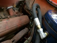
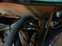
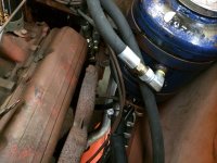
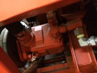
All done. Few trips to tractor supply fastenal grainger and Simpsons and we are back in business. All hoses changed fluid and rerouted the returns for a cleaner install.

P in the a but done. Not much room between exhaust manifold and orbitrol valve.

Creative fittings. . Will send pics.
 
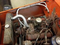
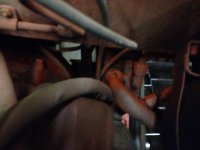
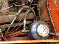
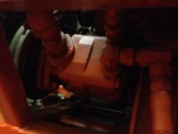
Here are the pics. System all better.
 

Attachments

  • IMG_0613.jpg
    IMG_0613.jpg
    47.1 KB · Views: 216
  • IMG_0614.jpg
    IMG_0614.jpg
    51.3 KB · Views: 215
  • IMG_0615.jpg
    IMG_0615.jpg
    69.6 KB · Views: 215
  • IMG_0616.jpg
    IMG_0616.jpg
    46.2 KB · Views: 218
  • IMG_0682.jpg
    IMG_0682.jpg
    71.6 KB · Views: 220
  • IMG_0683.jpg
    IMG_0683.jpg
    41.5 KB · Views: 212
  • IMG_0684.jpg
    IMG_0684.jpg
    75.9 KB · Views: 226
  • IMG_0685.jpg
    IMG_0685.jpg
    35.6 KB · Views: 206
I know this is an OLD thread, but its as good as any for asking my question: Once you replaced all your hoses, how did you bleed the system?
 
Let the pump run and make full turns left and right to get the air out of the piston and orbitrol.

It self bleeds the return loop once running.
 
Thank you @Track Addict and @DAVENET
My 1644 has the V20P pump with a 1-1/4" inlet. The hose has a leak. I'm assuming the hose is also 1-1/4" unless tucker adapter it up a size. Can't read any of the numbers on the hose. Just that it's made in the USA.
 
Tucker did lots of interesting things. Even welded fittings and nipples to make one of a kinds.

Best do take apart confirm then order.
 
Yank it off and take it to a hydraulic shop. They will have all of the oddball stuff (if any) needed to make a new one.
 
If you have any large size logging operations around you or contractors they usually have hose machines for making their own hoses . We have one at our shop and fixing leaking hoses is simple. Our local auto parts store also has one.
 
Thank you @Track Addict and @DAVENET
My 1644 has the V20P pump with a 1-1/4" inlet. The hose has a leak. I'm assuming the hose is also 1-1/4" unless tucker adapter it up a size. Can't read any of the numbers on the hose. Just that it's made in the USA.
I don't know what year your Tucker is, or the hydraulic hose configuration, so this may, or may not, be helpful.

On the 1979/1980 Tuckers I've owned (318 CID engines) the hydraulic tank is mounted on the right side and the Vickers pump is also on the right side. The fluid supply hose was 1 1/2" and Tucker used simple barbed fittings, and simple worm gear style hose clamps. The original hose was a generic Gates hose made for all kinds of uses. It's just static pressure, so just about any hose would work. The fittings on the hydraulic tank were not hydraulic fittings, but rather cheap standard threaded plumbing fittings.

On the 1986 Tucker (360 CID engine) the tank is in the same place, but the pump is on the left side. Tucker upgraded the fittings to hydraulic fittings, the hose has crimped on hydraulic fittings and the hose is covered with a braided heat/fire resistant cover. The hose runs behind the engine and is much longer.

We have completely re-plumbed the hydraulic lines on our CHUGSzilla project (that machine also has a front blade). I bought two 100' lengths of 1/2" hydraulic hose from Amazon/ebay and I sourced the crimp on fittings from a company in South Carolina called Hose in a Hurry. Scott and I determine the exact length of the hose we need and cut that from the bulk roll. We push the crimp on fittings into the hose ends and I take the semi-assembled hose to a local hydraulic company in SLC and they charge me a few bucks to do the crimping.
 
Got it. Your hydraulic system includes a Vickers pump, steering mechanism, and Garret tank with a filter. The pump delivers fluid to steering and other parts. The tank's suction line maintains flow to the steering, preventing cavitation. When replacing hoses and bypassing rear hydraulics, ensure proper sizing and installation for efficiency. Let me know if you need more help!
 
You mentioned a hydraulic filter. I replaced the filter and used NAPA 1196 but it made the hydraulic buzz and a seam started to leak.
Switched to Baldwin BT839 no more problems.
 
Top