Some months ago a new forum member started a thread inquiring about purchasing a used axle assembly for a Tucker with a broken axle housing. Reading the thread and looking at the photos revealed this was the machine Scott and I had re-cabbed and sold several years ago. Here's that machine.

In addition to the cab modifications, we did a bunch of work to it - basically repairing anything and everything we found wrong. After talking with Scott, I made the offer that if you bring us the machine - we’ll fix the axle housing at zero labor cost. Here’s a link to that thread: http://www.forumsforums.com/3_9/showthread.php?t=78490&highlight=tucker+1642+axle
The Tucker showed up toward the end of October and the owner requested we perform some additional repairs and maintenance. But the first order of business was the axle housing, and that’s the primary focus of this thread.
We removed the track, the track slide, sprocket hub and the carrier while leaving the machine on the trailer. I left to spend a few days in Southern Utah and Scott and a mutual friend, John worked on the axle repair in my absence. To get better access to evaluate the damage, as well as to make the repairs, they decided to unbolt the axle assembly from the springs, and subsequently decided to remove the axle assembly from the Tucker altogether. They supported the rear of the machine on pipe stands, and then used ratchet straps in a criss-cross pattern to secure the rear of the machine in place on the trailer. They then removed the axle housing with the left rear track and carrier still fully intact on the axle housing.
Here’s the machine with the right carrier and associated parts removed.

In this photo you can see the journal is bent up from the axle housing at an unnatural angle.

Here's a close-up of the cracked housing.

The journal end of the cracked housing has been cut away, revealing how little was holding it.

Here’s the journal side of the damaged housing.

Here’s the rear axle assembly with the left rear carrier still attached after removal from the trailer.

The Tucker on pipe stands.

As mentioned, I was away at the time, so I’m relating what was told to me. Scott decided to remove the carrier and track from the left side to make it easier to work with just the axle housing. After thoroughly cleaning the fractured area, Scott welded a sleeve inside the axle housing to the differential side, which protruded several inches in both directions. He then carefully positioned the journal side of the axle housing over the sleeve and ensured it was correctly aligned vertically, horizontally and rotationally, and he adjusted the in-and-out spacing, as well. At that point he welded the journal side to the sleeve. All of this was in preparation to join the broken parts. By having the sleeve in place it makes sure the weld goes all the way to the bottom of the housing. Without a sleeve, there’s nothing to weld to, and though one could "fill the gap”, the weld wouldn’t necessarily be as complete, or as strong. Interestingly, the axle housing “tubes" are not tubular steel, but are actually cast steel. Prior to welding that, Scott used an acetylene torch to heat the housing on both sides and then made multiple passes to get a full penetration weld rejoining the damaged sections. Normally after welding something, he breaks out one of his angle grinders and “cleans up” the weld, but other than some very minor clean up, he wanted to leave all the weld beads in place for maximum strength. (Incidentally, I queried Tucker as to the approximate cost of having them replace a broken Dana 60 axle housing. The answer was it depends on exactly what else has to be done to the axle assembly, but they wouldn’t do the job unless it was done “right” (totally understandable). The estimated cost was between $10K and $15K. Ouch!)
At this point I was back home and when I went to his shop I saw the repaired housing. We decided to inspect the rest of the housing for any other damage and we found a crack in the housing on the left side where the differential casting meets the axle tube, and we found cracks in both journals and in the spring perches, too - all of which we fixed.
Here’s a photo of the repaired axle housing.

Here’s the crack in the axle housing on the other side.

One of the cracked journals.

The crack “Vee’d out” prior to welding. (Yes, the surface the seal rides on will get a Speedi Sleeve.)

After welding, grinding and sanding to get the shape and contour correct.
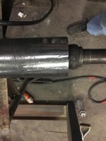
After grinding out the crack in the axle housing and heating it prior to welding.

After welding and minor cleanup.

Unfortunately, we weren’t done. Rotating the pinion yoke by hand, we detected a roughness that shouldn’t be there, suggesting a bad pinion bearing. We removed the differential carrier and ring gear, and then the pinion gear as well. All four tapered roller bearings, and their races were worn and needed to be replaced. We purchased a complete rebuild kit and replaced the above mentioned bearings, and also we re-shimmed the pinion and the differential carrier during reassembly. A new pinion seal, new washer and pinion nut completed the repair. BTW, the pinion nut torque is substantial (240-300 ft lbs), and depending on the individual pinion yoke casting, it can be difficult to get a socket inside the yoke and around the pinion nut to full depth. When your pulling on a torque wrench to 300 ft lbs, you really don’t want your socket to slip. The pinion nut size is 1 5/16 and a few years go I asked my machinist friend in Vermont to turn down the OD slightly of an impact socket for better clearance. The modified socket works great!

At this point I’d like to say “...and the axle assembly was ready to give several years of trouble free service”... except I can’t. The journals on the axle housing had significant wear. Replacing journals is both time consuming and expensive. However, as Track Addict explained in his excellent thread, one can use a product called bearing tape to add life to worn journals. Neither Scott nor I have used this, and I spoke to both Jeff Godard and Sterling Mathis at Tucker about the product. Presently Sterling is manager of the Parts Department, but previously he was the Service Department manager.
If you look at an older rubber belted Tucker from straight ahead or straight behind, especially one with worn journals, the carriers may look splayed out. What happens is the weight of the machine and the way it transfers that weight to the carriers causes the journals to wear on the outside bottom of the journal, and the inside on the top part. Over time as the clearance grows - it just gets worse. Sometimes you’ll see a machine with one, or more, inner drive sprockets rubbing against their respective carriers; because the carrier is no longer perpendicular with the axle housing. To correct this condition, bearing tape can be used to essentially shim the carrier into proper alignment. The bearing tape is quite thin, and it's made of a low-friction material with adhesive on the back side. The adhesive is covered by paper, which is removed just prior to installation.
Never having used it before, I wanted to know how Tucker does it, and Sterling Mathis explained: You start by removing anything and everything on the journal in terms of old grease, crud, etc. Then you use a stainless steel wire wheel to remove anything you missed. At that point, wipe the journal down with lacquer thinner or a similar solvent to give the bearing tape a pristine surface to adhere to. One buys the bearing tape from Tucker by the foot. You cut it into 2” wide strips and you wrap the journal around the circumference. Sterling suggested making the wraps about 2-3” from the journal ends, and if necessary make multiple wraps to build up the thickness. The carrier should fit very tightly over the journal with minimal clearance. Sterling said they fabricated a tool that fits over the axle spindle and against the carrier’s outside end, and they then use the spindle nut to persuade the carrier into position. He said though seemingly it’s initially too tight, the weight of the machine will make the carrier rotate on the journal as it should, and it will wear into a proper fit.
Scott and I decided to take some measurements to see just how much wear there was. We took measurements of the journal vertically and horizontally, on the inside and on the outside of the journal. There’s little wear on the sides, the vast majority is (again) on the bottom outside and the top inside. But just how egg-shaped is the wear pattern? On the inside the horizontal measurement was 5.140 and the vertical was 5.081. The outside measurements were horizontal 5.127 and vertical 5.051. If you assumed zero wear on the inside horizontal at 5.140, and compared that to the outside vertical measurement of 5.051, that’s .089 or almost 3/32” of steel that’s been worn away. That’s a lot!
We thoroughly cleaned the journal, and we cleaned the inside of the carrier as well. After cleaning everything from inside of the carrier, the surface still felt somewhat rough. Scott used a dingleberry hone for a huge Cummins cylinder he had on hand, and used that to clean up the inside of the carrier. The journals are steel, which is a lot harder than the low-friction plastic bearing tape, and if the surface that rides on the bearing tape is at all rough, it would seem it would wear the tape in no time.
We tried using the factory’s procedure as explained, but even with only one circumferential wrap there wasn’t enough clearance on the sides (where there’s very little wear) to slide the carrier on. We discussed the situation and came up with an alternate method we think is more logical: The objective of installing bearing tape is twofold: to reduce the excessive clearance between the carrier and the journal on the axle, and to correct the misalignment caused by the wear pattern. Adding bearing tape circumferentially adds tape to areas that have very little wear. While that does reduce the excessive clearance, it also maintains the misalignment. Scott and I chose to locate the tape in the high wear areas, and put no tape where there was no/minimal wear on the journal. We also decided to position the tape right on the edge of the journal, where the wear is greatest, instead of 2-3” back from the edge as suggested. We did this with some trepidation. We have a lot of respect for Tucker’s recommendations, and deviating from them may be ill-advised. But after a lot of back and forth discussion, we went with our plan.
We cut the bearing tape into two inch widths per Sterling’s recommendation. We cut our first layer 3.5” long and installed the two pieces parallel with the journal on the bottom outside and the top inside. Then we cut four pieces 2.5” long and put them parallel with the journal overlapping the first layer by one inch and on either side of the first layer (the pic below will make sense). Then a length 5” long installed perpendicular to the other pieces, and extending past them equally. On the outside bottom we added a fourth piece 6” long installed perpendicular as well, and also overlapping the previous piece equally. We measured the thickness of the bearing tape with the adhesive backing paper removed at .022. So we added .088 on the bottom outside and .066 on the top inside, which would bring the bottom outside measurement to 5.139 and the top inside to 5.147.
Here’s a pic of the outside bottom with the first layer 3.5” long, and the second layer’s two strips laid side by side and 2.5” long. Subsequent layer(s) were installed perpendicular to these.

Here’s the journal with the next layer added.

Our pattern concentrates the tape where the wear is greatest, and yet tapers the thickness of the bearing tape as the journal’s wear pattern is reduced. Not exact, but a reasonable approximation. Realize too, the tape’s thickness is somewhat limiting as you can’t shim less than .022. I wish I could say we’ve used this for hundreds of hours on the machine, with minimal wear and great success, but this is our first experience.
We sprayed some white lithium grease on our taped journal to make the carrier slide more easily during installation, and then slid the carrier onto the journal. It wasn’t exactly easy-peazy. The axle housing was supported on horses and we had the carrier suspended with the shop’s crane. I tried to hold the axle housing while Scott both pushed-on and rotated the carrier.

We discussed our procedure afterward and concluded we really wouldn’t want the carrier to fit more tightly. There’s a tiny bit of play, but it would be difficult to get it to fit much tighter, and what if you’ve forced the carrier onto the journal - and then have to remove it?

In addition to the cab modifications, we did a bunch of work to it - basically repairing anything and everything we found wrong. After talking with Scott, I made the offer that if you bring us the machine - we’ll fix the axle housing at zero labor cost. Here’s a link to that thread: http://www.forumsforums.com/3_9/showthread.php?t=78490&highlight=tucker+1642+axle
The Tucker showed up toward the end of October and the owner requested we perform some additional repairs and maintenance. But the first order of business was the axle housing, and that’s the primary focus of this thread.
We removed the track, the track slide, sprocket hub and the carrier while leaving the machine on the trailer. I left to spend a few days in Southern Utah and Scott and a mutual friend, John worked on the axle repair in my absence. To get better access to evaluate the damage, as well as to make the repairs, they decided to unbolt the axle assembly from the springs, and subsequently decided to remove the axle assembly from the Tucker altogether. They supported the rear of the machine on pipe stands, and then used ratchet straps in a criss-cross pattern to secure the rear of the machine in place on the trailer. They then removed the axle housing with the left rear track and carrier still fully intact on the axle housing.
Here’s the machine with the right carrier and associated parts removed.

In this photo you can see the journal is bent up from the axle housing at an unnatural angle.

Here's a close-up of the cracked housing.

The journal end of the cracked housing has been cut away, revealing how little was holding it.

Here’s the journal side of the damaged housing.

Here’s the rear axle assembly with the left rear carrier still attached after removal from the trailer.

The Tucker on pipe stands.

As mentioned, I was away at the time, so I’m relating what was told to me. Scott decided to remove the carrier and track from the left side to make it easier to work with just the axle housing. After thoroughly cleaning the fractured area, Scott welded a sleeve inside the axle housing to the differential side, which protruded several inches in both directions. He then carefully positioned the journal side of the axle housing over the sleeve and ensured it was correctly aligned vertically, horizontally and rotationally, and he adjusted the in-and-out spacing, as well. At that point he welded the journal side to the sleeve. All of this was in preparation to join the broken parts. By having the sleeve in place it makes sure the weld goes all the way to the bottom of the housing. Without a sleeve, there’s nothing to weld to, and though one could "fill the gap”, the weld wouldn’t necessarily be as complete, or as strong. Interestingly, the axle housing “tubes" are not tubular steel, but are actually cast steel. Prior to welding that, Scott used an acetylene torch to heat the housing on both sides and then made multiple passes to get a full penetration weld rejoining the damaged sections. Normally after welding something, he breaks out one of his angle grinders and “cleans up” the weld, but other than some very minor clean up, he wanted to leave all the weld beads in place for maximum strength. (Incidentally, I queried Tucker as to the approximate cost of having them replace a broken Dana 60 axle housing. The answer was it depends on exactly what else has to be done to the axle assembly, but they wouldn’t do the job unless it was done “right” (totally understandable). The estimated cost was between $10K and $15K. Ouch!)
At this point I was back home and when I went to his shop I saw the repaired housing. We decided to inspect the rest of the housing for any other damage and we found a crack in the housing on the left side where the differential casting meets the axle tube, and we found cracks in both journals and in the spring perches, too - all of which we fixed.
Here’s a photo of the repaired axle housing.

Here’s the crack in the axle housing on the other side.

One of the cracked journals.

The crack “Vee’d out” prior to welding. (Yes, the surface the seal rides on will get a Speedi Sleeve.)

After welding, grinding and sanding to get the shape and contour correct.

After grinding out the crack in the axle housing and heating it prior to welding.

After welding and minor cleanup.

Unfortunately, we weren’t done. Rotating the pinion yoke by hand, we detected a roughness that shouldn’t be there, suggesting a bad pinion bearing. We removed the differential carrier and ring gear, and then the pinion gear as well. All four tapered roller bearings, and their races were worn and needed to be replaced. We purchased a complete rebuild kit and replaced the above mentioned bearings, and also we re-shimmed the pinion and the differential carrier during reassembly. A new pinion seal, new washer and pinion nut completed the repair. BTW, the pinion nut torque is substantial (240-300 ft lbs), and depending on the individual pinion yoke casting, it can be difficult to get a socket inside the yoke and around the pinion nut to full depth. When your pulling on a torque wrench to 300 ft lbs, you really don’t want your socket to slip. The pinion nut size is 1 5/16 and a few years go I asked my machinist friend in Vermont to turn down the OD slightly of an impact socket for better clearance. The modified socket works great!

At this point I’d like to say “...and the axle assembly was ready to give several years of trouble free service”... except I can’t. The journals on the axle housing had significant wear. Replacing journals is both time consuming and expensive. However, as Track Addict explained in his excellent thread, one can use a product called bearing tape to add life to worn journals. Neither Scott nor I have used this, and I spoke to both Jeff Godard and Sterling Mathis at Tucker about the product. Presently Sterling is manager of the Parts Department, but previously he was the Service Department manager.
If you look at an older rubber belted Tucker from straight ahead or straight behind, especially one with worn journals, the carriers may look splayed out. What happens is the weight of the machine and the way it transfers that weight to the carriers causes the journals to wear on the outside bottom of the journal, and the inside on the top part. Over time as the clearance grows - it just gets worse. Sometimes you’ll see a machine with one, or more, inner drive sprockets rubbing against their respective carriers; because the carrier is no longer perpendicular with the axle housing. To correct this condition, bearing tape can be used to essentially shim the carrier into proper alignment. The bearing tape is quite thin, and it's made of a low-friction material with adhesive on the back side. The adhesive is covered by paper, which is removed just prior to installation.
Never having used it before, I wanted to know how Tucker does it, and Sterling Mathis explained: You start by removing anything and everything on the journal in terms of old grease, crud, etc. Then you use a stainless steel wire wheel to remove anything you missed. At that point, wipe the journal down with lacquer thinner or a similar solvent to give the bearing tape a pristine surface to adhere to. One buys the bearing tape from Tucker by the foot. You cut it into 2” wide strips and you wrap the journal around the circumference. Sterling suggested making the wraps about 2-3” from the journal ends, and if necessary make multiple wraps to build up the thickness. The carrier should fit very tightly over the journal with minimal clearance. Sterling said they fabricated a tool that fits over the axle spindle and against the carrier’s outside end, and they then use the spindle nut to persuade the carrier into position. He said though seemingly it’s initially too tight, the weight of the machine will make the carrier rotate on the journal as it should, and it will wear into a proper fit.
Scott and I decided to take some measurements to see just how much wear there was. We took measurements of the journal vertically and horizontally, on the inside and on the outside of the journal. There’s little wear on the sides, the vast majority is (again) on the bottom outside and the top inside. But just how egg-shaped is the wear pattern? On the inside the horizontal measurement was 5.140 and the vertical was 5.081. The outside measurements were horizontal 5.127 and vertical 5.051. If you assumed zero wear on the inside horizontal at 5.140, and compared that to the outside vertical measurement of 5.051, that’s .089 or almost 3/32” of steel that’s been worn away. That’s a lot!
We thoroughly cleaned the journal, and we cleaned the inside of the carrier as well. After cleaning everything from inside of the carrier, the surface still felt somewhat rough. Scott used a dingleberry hone for a huge Cummins cylinder he had on hand, and used that to clean up the inside of the carrier. The journals are steel, which is a lot harder than the low-friction plastic bearing tape, and if the surface that rides on the bearing tape is at all rough, it would seem it would wear the tape in no time.
We tried using the factory’s procedure as explained, but even with only one circumferential wrap there wasn’t enough clearance on the sides (where there’s very little wear) to slide the carrier on. We discussed the situation and came up with an alternate method we think is more logical: The objective of installing bearing tape is twofold: to reduce the excessive clearance between the carrier and the journal on the axle, and to correct the misalignment caused by the wear pattern. Adding bearing tape circumferentially adds tape to areas that have very little wear. While that does reduce the excessive clearance, it also maintains the misalignment. Scott and I chose to locate the tape in the high wear areas, and put no tape where there was no/minimal wear on the journal. We also decided to position the tape right on the edge of the journal, where the wear is greatest, instead of 2-3” back from the edge as suggested. We did this with some trepidation. We have a lot of respect for Tucker’s recommendations, and deviating from them may be ill-advised. But after a lot of back and forth discussion, we went with our plan.
We cut the bearing tape into two inch widths per Sterling’s recommendation. We cut our first layer 3.5” long and installed the two pieces parallel with the journal on the bottom outside and the top inside. Then we cut four pieces 2.5” long and put them parallel with the journal overlapping the first layer by one inch and on either side of the first layer (the pic below will make sense). Then a length 5” long installed perpendicular to the other pieces, and extending past them equally. On the outside bottom we added a fourth piece 6” long installed perpendicular as well, and also overlapping the previous piece equally. We measured the thickness of the bearing tape with the adhesive backing paper removed at .022. So we added .088 on the bottom outside and .066 on the top inside, which would bring the bottom outside measurement to 5.139 and the top inside to 5.147.
Here’s a pic of the outside bottom with the first layer 3.5” long, and the second layer’s two strips laid side by side and 2.5” long. Subsequent layer(s) were installed perpendicular to these.

Here’s the journal with the next layer added.

Our pattern concentrates the tape where the wear is greatest, and yet tapers the thickness of the bearing tape as the journal’s wear pattern is reduced. Not exact, but a reasonable approximation. Realize too, the tape’s thickness is somewhat limiting as you can’t shim less than .022. I wish I could say we’ve used this for hundreds of hours on the machine, with minimal wear and great success, but this is our first experience.
We sprayed some white lithium grease on our taped journal to make the carrier slide more easily during installation, and then slid the carrier onto the journal. It wasn’t exactly easy-peazy. The axle housing was supported on horses and we had the carrier suspended with the shop’s crane. I tried to hold the axle housing while Scott both pushed-on and rotated the carrier.

We discussed our procedure afterward and concluded we really wouldn’t want the carrier to fit more tightly. There’s a tiny bit of play, but it would be difficult to get it to fit much tighter, and what if you’ve forced the carrier onto the journal - and then have to remove it?


